
Incinerator

A technology for incinerators and furnace bodies, applied in the field of incinerators, which can solve problems such as fast burning speed, formation of yellow flames, inconvenient fuel addition, etc., and achieve the effects of convenient fuel addition, stable fuel combustion, and easy fire control

Active Publication Date: 2014-01-22
宁波科莱尔节能科技股份有限公司
View PDF7 Cites 2 Cited by
  • Summary
  • Abstract
  • Description
  • Claims
  • Application Information

AI Technical Summary

Problems solved by technology

Among them, the lower part of the bonfire combustion is the combustion area, that is, the bottom-up area is the carbonization area, the combustion area and the fuel area. The temperature of the carbonization area and the combustion area is relatively high. Or a large amount of unburned fuel is heated and vaporized, and then a large amount of newly added or unburned fuel participates in combustion. At this time, due to the low oxygen content of the high-temperature gas in the combustion zone, the vaporized combustible gas cannot be combusted normally due to the obvious lack of air. , leading to the generation of a large amount of free carbon, black smoke or yellow flame will appear at this time, the flame temperature is low at this time, and energy waste is obvious
Therefore, this kind of bonfire-style combustion has the characteristics of fast burning speed, difficult control, and the fuel is quickly burned out. The cooker disclosed in the patent document with the above-mentioned announcement number CN201844426U is a bonfire-style combustion structure.
[0004] The candle combustion is burning from top to bottom, that is, from top to bottom are the combustion zone, carbonization zone, melting and vaporization zone and fuel zone, in which the fuel zone has a lower temperature, the carbonization zone and combustion zone have higher temperatures, and the melting and vaporization zone The temperature is close to the temperature of the carbonization zone and the combustion zone. The flame heats the fuel below while burning. This combustion method has little energy waste, and most of the vaporized combustible gas participates in the combustion. The combustion is easy to control, but it is inconvenient to add fuel. If fuel is added from above the flame, it will inevitably cover the flame, and the defects of the above-mentioned campfire combustion will occur again.
[0005] Flat-push combustion is common in rural earthen stoves. The firewood is pushed into the combustion chamber from the feeding port. The front end of the firewood burns, and the rear end is vaporized while preheating, and then enters the combustion state one by one. This method needs to be continuously pushed by humans. Firewood is difficult to control, and the size of the flame is affected by the artificial addition of firewood, which is extremely unstable. During the process of adding firewood, it is also very likely that the above-mentioned black smoke or yellow flame phenomenon in the bonfire-style combustion will appear

Method used


Image

  • Incinerator
  • Incinerator
  • Incinerator

Examples


no. 1 example

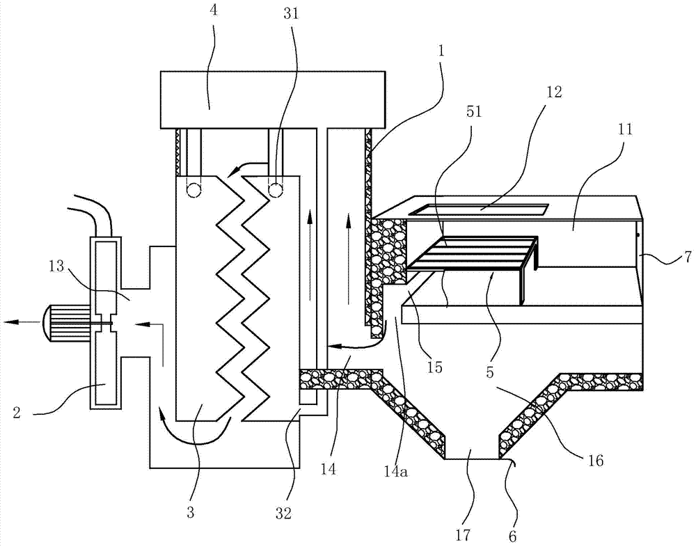
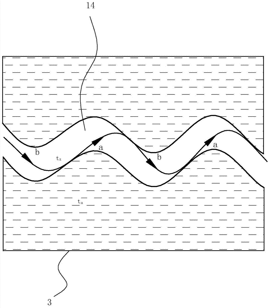
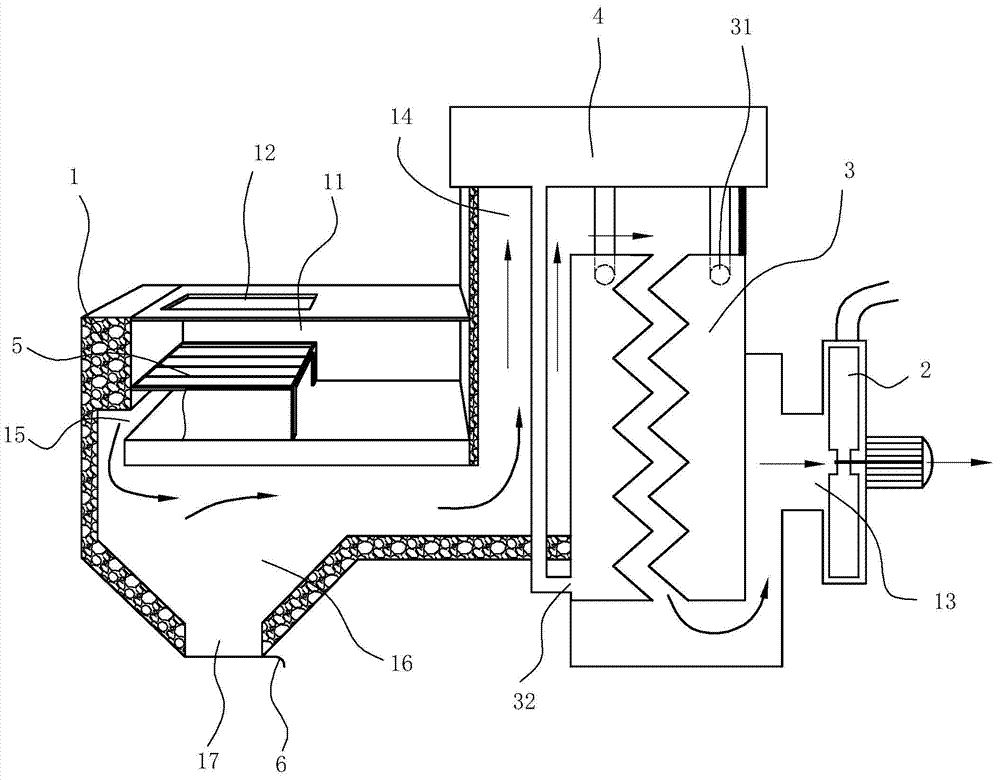
[0021] The first embodiment, such as figure 1 and figure 2 , the incinerator includes a furnace body 1, a combustion chamber 11 positioned in the furnace body, a charging port 12 communicating with the combustion chamber 11, and an exhaust port 13 located on the furnace body and equipped with an exhaust fan 2, the exhaust port 13 The furnace body between the combustion chamber 11 has an exhaust passage 14 for heat exchange with the heated body, wherein the feeding port 12 is located above the combustion chamber 11, and the feeding port is exposed on the top surface of the furnace body, and the feeding port is also used as an inlet. Tuyere: The lower part of the combustion chamber 11 has a smoke outlet 15 communicating with the exhaust passage 14 . In this embodiment, there is a gap between the left side of the combustion chamber 11 and the bottom, which may also be formed by a designed gap at the bottom of the left side of the combustion chamber.

[0022] In this embodiment...


PUM


Abstract

The invention relates to an incinerator. The incinerator comprises an incinerator body, a combustion chamber arranged in the incinerator body, a feed port communicated with the combustion chamber, and an exhaust port provided with an exhaust blower, wherein an exhaust channel which exchanges heat with a heated body is arranged in the portion, between the exhaust port and the combustion chamber, inside the incinerator body. The incinerator is characterized in that the feed port is an air inlet and located above the combustion chamber, the lower portion of the combustion chamber is provided with a smoke discharge port communicated with the exhaust channel, meanwhile, a combustion bed which covers the smoke discharge port is placed at the bottom of the combustion chamber, the upper surface of the combustion bet is design into a grid, vent holes which are communicated with the smoke discharge port are formed in two side faces, corresponding to the smoke discharge port, of the combustion bed respectively, other side faces of the combustion bed are closed, and therefore a combustion area above the grid and a smoke and dust discharge area below the grid are formed in the combustion chamber. By the adoption of the structure, the incinerator has the advantages that full combustion can be achieved, no black smoke is produced, firewood can be conveniently added, combustion is stable and controllable, and the smoke can be smoothly discharged.

Description

technical field [0001] The invention relates to a stove, in particular to an incinerator. Background technique [0002] Existing furnace (or stove) is of a great variety, and it generally comprises body of heater, is positioned at the combustion chamber of furnace body and the charging port that communicates with combustion chamber. At the same time, a water tank is also provided in the furnace body. For example, the Chinese patent authorization announcement number is CN201606905U and the Chinese patent authorization announcement number is CN201844426U, which both disclose specific furnace (or stove) devices. [0003] But no matter what the structure is, according to the burning method of its fuel, it can be divided into campfire burning, candle burning and flat push burning. Among them, the lower part of the bonfire combustion is the combustion area, that is, the bottom-up area is the carbonization area, the combustion area and the fuel area. The temperature of the carboni...

Claims


Application Information

Patent Timeline
Patent Type & Authority Applications(China)
IPC IPC(8): F24B1/18F24B1/189F24B1/191F24B1/192F24B1/197
Inventor 陈立德陈诗
Owner 宁波科莱尔节能科技股份有限公司
Learn More