Linear displacement laser interferometer calibrating method and device based on four-standard optical axis

A technology of laser interferometer and laser interference, which is applied in the direction of using optical devices, measuring devices, instruments, etc., can solve the problems of large Abbe error, unequal optical path, and inconsistent influence, etc., and achieve the effect of small Abbe error

Active Publication Date: 2014-01-22
HARBIN INST OF TECH
View PDF3 Cites 4 Cited by
  • Summary
  • Abstract
  • Description
  • Claims
  • Application Information

AI Technical Summary

Problems solved by technology

Since the two sets of laser interferometers are placed in parallel, the two paths of light are similarly affected by the environment, and the refractive index of air has little influence on the two paths of light. Big error
[0004] figure 2 It is a schematic diagram of the face-to-face laser interferometer calibration device. The standard measuring mirror and the calibrated measuring mirror are installed on the moving platform face to face. The advantage is that the measuring beam axes of the two sets of laser interferometers can be adjusted to almost the same measuring axis. The Abbe error is very small. The disadvantage is that the near end of one interferometer is the far end of the other.
[0005] In 2011, the National Institute of Metrology established the first 80-meter long-length laser interferometer measurement device in China (Leng Yuguo, Tao Lei, Xu Jian. Analysis of the accuracy and influencing factors of the dual-frequency laser interferometer system based on the 80-meter measurement device. Metrology and Testing Technology, 2011, 38(9): 47-49), the standard device used is to place three Agilent5530 long-distance dual-frequency laser interferometers in parallel to form a three-way

Method used


Image

  • Linear displacement laser interferometer calibrating method and device based on four-standard optical axis
  • Linear displacement laser interferometer calibrating method and device based on four-standard optical axis
  • Linear displacement laser interferometer calibrating method and device based on four-standard optical axis

Examples


Embodiment Construction

[0025] The specific embodiments of the present invention will be further described in detail below in conjunction with the accompanying drawings.

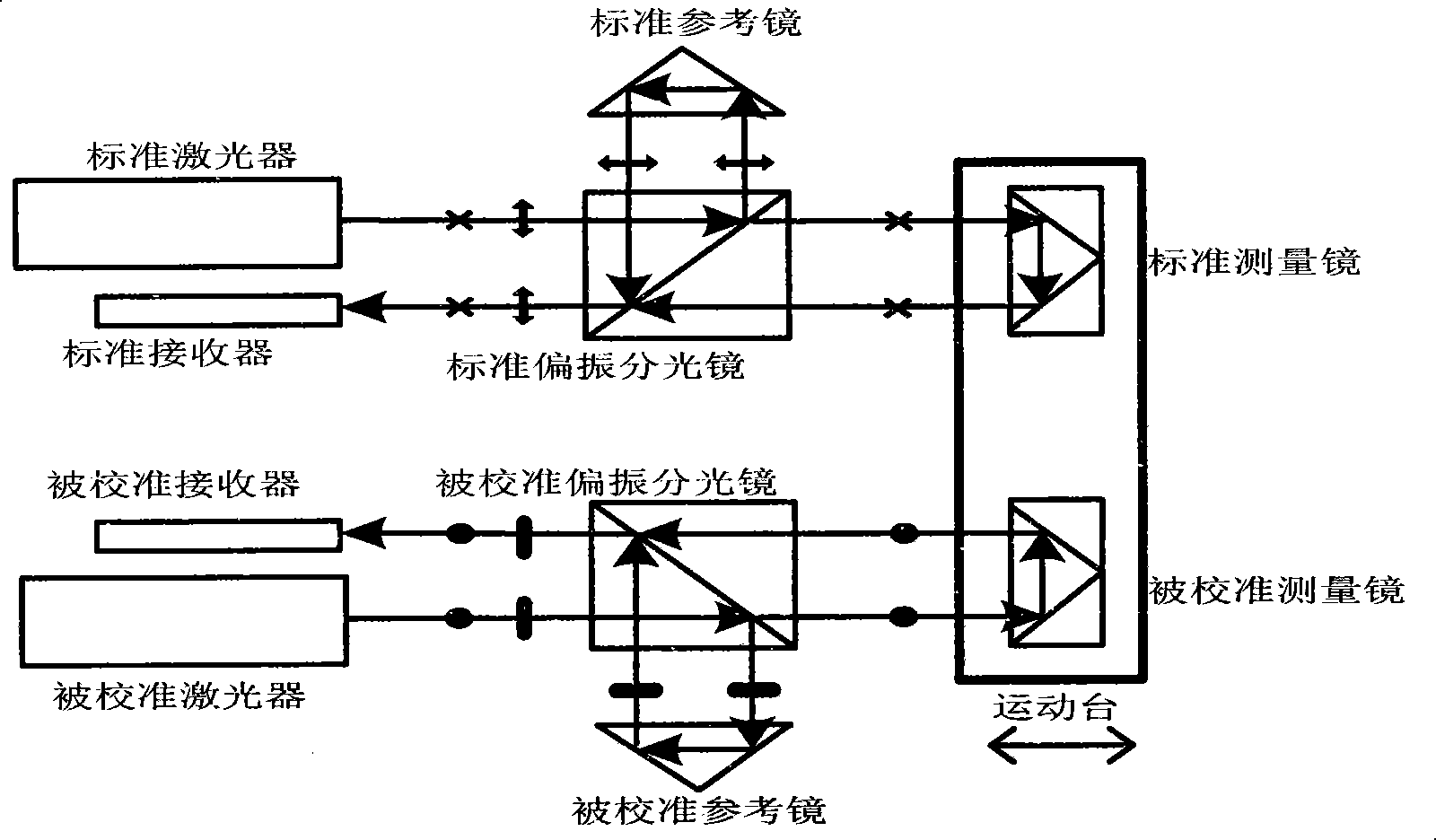
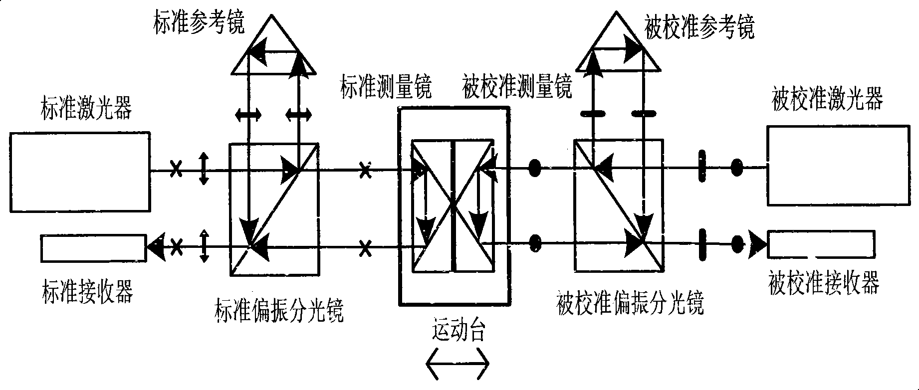
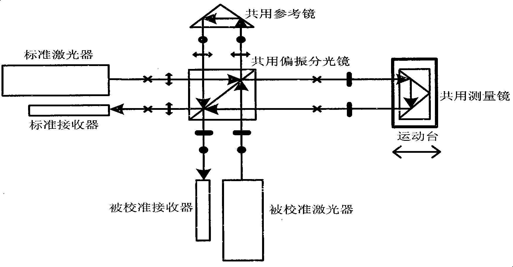
[0026]A linear-displacement laser interferometer calibration device based on four standard optical axes, including a standard laser interferometer laser 1 and four lasers arranged at positions that can respectively receive four parallel standard measurement beams 3, 4, 5, and 6 corresponding to the interference signals Receivers 8, 9, 10, 11, the wires connect the four receivers 8, 9, 10, 11 to the standard laser interferometer signal processing system 12 respectively; an intermediate through hole is arranged on the output optical path of the standard laser interferometer laser 1 16 four-axis hollow standard laser interference mirror group 2 that allows the calibrated laser interferometer measurement beam 15 to pass through; one side of the four-axis hollow standard laser interference mirror group 2 is equipped with a guide rail 21,...


PUM


Abstract

The invention discloses a linear displacement laser interferometer calibrating method and device based on a four-standard optical axis, and belongs to the technical field of laser measurement. Measuring light beams of a calibrated laser interferometer pass through the middle through hole of a four-axle hollow laser interference mirror group; the measuring light beams of the calibrated laser interferometer are arranged in parallel in the centers of four parallel standard measuring light beams which are distributed in the forms of lateral edges of a regular quadrangular prism; in a plane vertical to the four standard measuring light beams and in a square area formed by the projection points of the four standard measuring light beams on the plane, the difference between the environment interference degrees of the four standard measuring light beams and the measuring beams of the calibrated laser interferometer is very small, and the average value of the refractive indexes of the four standard measuring light beams is close to the air refractive index values of the measuring light beams of the calibrated laser interferometer.

Description

technical field [0001] The invention belongs to the technical field of laser measurement, and mainly relates to a laser interferometer calibration method and device. Background technique [0002] Laser interferometry linear displacement technology is a standard measurement technology with high precision. It is widely used in precision and ultra-precision machining, microelectronics equipment, nanotechnology industrial equipment and national defense equipment. In order to ensure the accuracy of laser interferometer measurement of linear displacement , requires a scientific and effective linear displacement laser interferometer calibration method and device. The general idea of ​​calibrating a linear displacement laser interferometer is to use a linear displacement laser interferometer with a higher level of precision for calibration. When the accuracy of the two is similar, it is called comparison. In the actual calibration work, most of the linear displacement laser interfe...

Claims


Application Information

Patent Timeline
IPC IPC(8): G01B9/02G01B11/02
Inventor 胡鹏程谭久彬
Owner HARBIN INST OF TECH
Why Eureka
Try Eureka