Micro hybrid light splitting device

A spectroscopic device and miniature technology, applied in the direction of measuring devices, spectrometry/spectrophotometry/monochromator, analytical materials, etc., to achieve the effect of wide volume, high spectroscopic, high wavelength resolution

Active Publication Date: 2014-01-22
XIAMEN UNIV
View PDF4 Cites 12 Cited by
  • Summary
  • Abstract
  • Description
  • Claims
  • Application Information

AI Technical Summary

Problems solved by technology

[0005] Aiming at the problems of the above-mentioned spectroscopic device, the present invention proposes a micro-hybrid spectroscopic device, which aims to make full use of the adv...

Method used


Image

  • Micro hybrid light splitting device
  • Micro hybrid light splitting device
  • Micro hybrid light splitting device

Examples


Embodiment 1

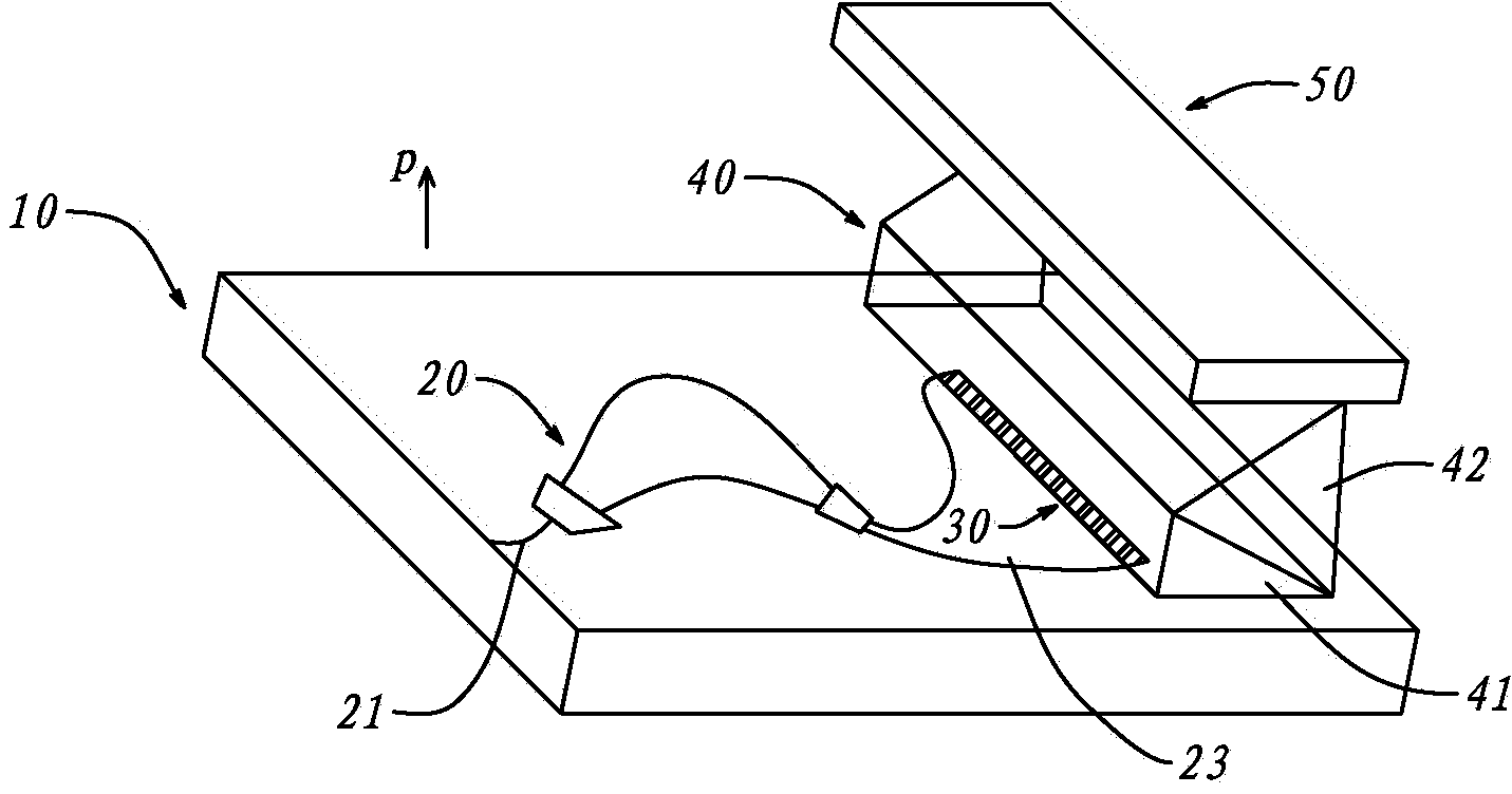
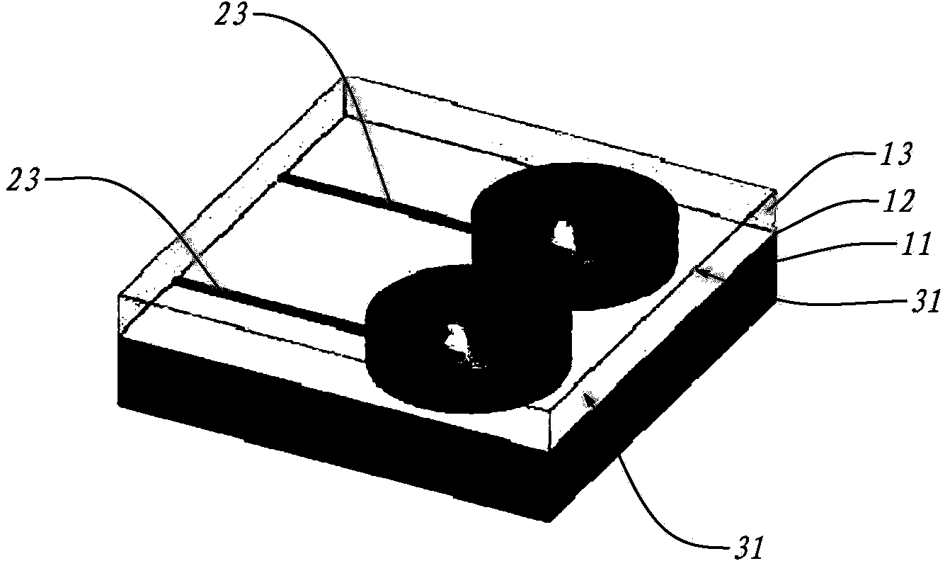
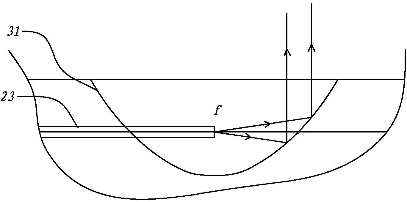
[0035] Such as Figure 1 to Figure 6 Shown, a series of schematic diagrams of Embodiment 1 of the present invention, wherein, figure 1 , figure 2 with image 3 Shows its main structure and its enlarged perspective view; Figure 4 with Figure 5 then shows the output spectrum of the output waveguide 23, Image 6 The spot projection obtained by the final spectroscopic is shown.

[0036] This embodiment is a micro-hybrid spectroscopic device, which includes a substrate 10 with an arrayed waveguide grating 20 on the substrate 10, and the arrayed waveguide grating has an input optical fiber and 40 output waveguides 23.

[0037] There is a mirror array 30 on the substrate 10 , and the mirror array 30 has 40 mirror bodies 31 , each mirror body 31 corresponds to the output waveguide 23 one by one. The exit area of ​​reflector array 30 has a prism assembly 40, and this prism assembly 40 rear stage has a photodetector array 50, and photodetector array 50 has photoelectric probe; ...

Embodiment 2

[0050] Such as Figure 7 Shown is a schematic diagram of Embodiment 2 of the present invention.

[0051] The substrate 10, arrayed waveguide grating 20, optical glue 41, and prism 42 of this embodiment are similar to those of the first embodiment, the difference is that there is another plane reflection device 60, which is arranged on the light-emitting surface of the prism 42, and the The light emitted from the light emitting surface of the prism 42 is reflected and then projected to the photodetector array 50 . This structure further improves the final light splitting effect and makes the light spots obtained on the photodetector array 50 more independent. This embodiment enables a more compact installation. The whole device is connected with the input optical fiber through the installable universal optical fiber connector, and it can be docked with the external probe without cumbersome optical alignment, realizing a compact and modular solution.


PUM

PropertyMeasurementUnit
Thicknessaaaaaaaaaa
Thicknessaaaaaaaaaa

Abstract

The invention discloses a micro hybrid light splitting device, which is characterized by comprising a substrate, wherein the substrate is provided with an arrayed waveguide grating, a reflecting mirror array, a prism assembly and a photoelectric detector array, wherein the arrayed waveguide grating is provided with an input optical fiber and n output waveguides; the reflecting mirror array is positioned on the substrate, and is provided with n reflecting mirror bodies which correspond to the output waveguides respectively; the prism assembly is arranged in the emitting area of the reflecting mirror array, and is used for splitting n strands of light rays from the reflecting mirror array into m strands respectively, and outputting; the photoelectric detector array is arranged at the back stage of the prism assembly. In the scheme, the prism assembly is taken as a back stage element of the arrayed waveguide grating working at multiple diffraction orders, so that light signals of multiple diffraction orders output by the output waveguides of the arrayed waveguide grating can be further dispersed longitudinally to form a light spot array on a focal plane where the photoelectric detector array is positioned, and the light signals are converted into digital signals through the photoelectric detector array. The device can be used for realizing light splitting in a wide wavelength range at a high wavelength resolution in a small volume.

Description

technical field [0001] The invention relates to a spectroscopic device with spectroscopic function for various types of spectrometers. Background technique [0002] Spectrometers can measure specific chemical components and have broad application prospects in food safety, medical and health, and environmental testing. At present, there are many commercial products of spectrometers, but these products still have the disadvantages of high price, low wavelength resolution, and large volume and weight in application. Promote the portability and expanded application of chemical analysis instruments, and effectively improve food and environmental safety at the level of testing technology. [0003] At present, most commonly used spectrometers use gratings or prisms to split light. Since gratings and prisms are angular dispersion elements, the larger the focal length, the higher the wavelength resolution, and the reduction in volume will directly reduce the focal length, thereby re...

Claims


Application Information

Patent Timeline
IPC IPC(8): G01J3/02G01N21/01G01J3/28
Inventor 吕苗邓盛锋程雅琴崔晓斌李一帆
Owner XIAMEN UNIV
Why Eureka
Try Eureka