High-speed ejection device for steel ball

A technology of ejection device and steel ball, which is applied in the direction of measuring device, impact test, machine/structural component test, etc., can solve the problems of uncontrollable steel ball launch speed and simple structure, and achieve high reliability, convenient operation and overall compact effect

Inactive Publication Date: 2014-01-22
SHANGHAI UNIV
View PDF7 Cites 8 Cited by
  • Summary
  • Abstract
  • Description
  • Claims
  • Application Information

AI Technical Summary

Problems solved by technology

The existing test device has a simple structure and uncontrollable steel ball launch speed

Method used


Image

  • High-speed ejection device for steel ball
  • High-speed ejection device for steel ball
  • High-speed ejection device for steel ball

Examples


Embodiment 2

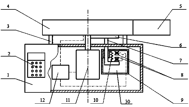
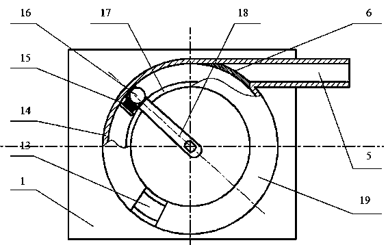
[0020] see Figure 1 to Figure 3 , this embodiment is basically the same as Embodiment 1, and the special feature is: the baffle push-pull device (30) includes two electromagnets (8), springs (10), push-pull rods (7) and push-pull device housings ( 9), the push-pull rod (7) passes through the guide groove in the push-pull device housing (9), and can move up and down along the guide groove. The electromagnet (8) is fixed on the top inside the push-pull device housing (9), and the electromagnet 2 (8) is fixed on the push-pull rod (7), and has an up-and-down position relationship with the electromagnet (8), and the two ends of the spring (10) are respectively connected with the top of the push-pull rod (7) and the push-pull device housing (9) , when the two electromagnets (8) are not energized, the spring (10) pulls the push-pull rod (7) up, and when the two electromagnets (8) are energized, the push-pull rod will be pushed up under the repulsion of the electromagnetic force (7)...


PUM


Abstract

The invention relates to a high-speed ejection device for a steel ball. The device comprises an operation keyboard and display, a rotating track, a sliding baffle, a pull rod, a pull rod controller, a motor, a master controller, an electromagnet sleeve, the steel ball and a rotating handle. When a speed required to be reached by the steel ball is set by the keyboard, the master controller controls the motor to rotate, and the steel ball speed is calculated; at the same time, the electromagnet sleeve is powered on, and the steel ball is absorbed so as to be prevented from falling; when the steel ball reaches a required speed, firstly, the master controller controls the pull rod controller to pull down the sliding baffle, the rotating track and an outlet are communicated, the electromagnet sleeve is powered off, and finally, the rotating speed of the motor is decreased, so that the steel ball and the electromagnet sleeve are separated, and the steel ball is ejected from the outlet along the rotating track under the action of the centrifugal force. The rotating speed of the motor is adjusted, so that the ejection speed of the steel ball can be changed very conveniently, and the adjustment range is very wide. The high-speed ejection device for the steel ball is compact in whole structure and convenient to operate, the steel ball speed can be controlled accurately, and the device has the advantages of high reliability and simple adjustment.

Description

technical field [0001] The invention relates to a high-speed steel ball ejection device, in particular to a steel ball high-speed ejection device for testing the impact resistance of protective masks or protective glasses. technical background [0002] Protective glasses are a kind of glasses that play a special role, and the glasses with different needs are different in the occasions used. The main function of protective glasses is to protect the eyes and face from the radiation of electromagnetic waves such as ultraviolet rays, infrared rays and microwaves, the damage of dust, smoke, metal and sand debris, and chemical solution sputtering. Therefore, protective masks, protective glasses or other glass products are often subject to impact testing. In the prior art, the impact test is carried out by hanging steel balls or falling steel balls, and the impact velocity of the steel balls is difficult to adjust and measure accurately. If the high-speed impact test is to be rea...

Claims


Application Information

Patent Timeline
Patent Type & Authority Applications(China)
IPC IPC(8): G01M7/08
Inventor 李阳金士良王俊杰潘绍斌王薇薇
Owner SHANGHAI UNIV
Why Eureka
Try Eureka