Power supply power distribution system and method
A technology for power distribution and DC power supply, which is applied to control/regulating systems, electrical components, regulating electrical variables, etc. It can solve the problems of high cost of AC UPS, high loss of transmission lines, large system harmonics, etc., and achieves simple structure, Low cost and low ripple effect
- Summary
- Abstract
- Description
- Claims
- Application Information
AI Technical Summary
Problems solved by technology
Method used
Image

Examples
Embodiment 1
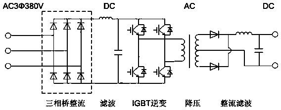
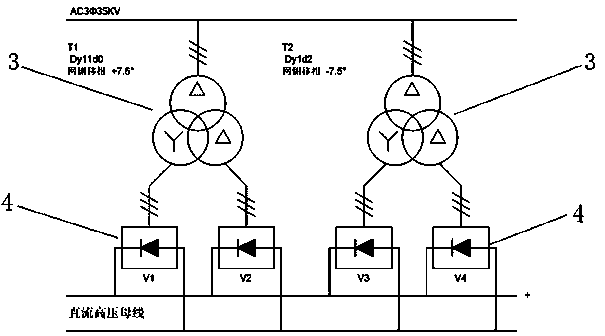
[0032] as attached image 3 , attached Figure 4 , attached Figure 5 As shown, the power distribution system of this embodiment includes a 24-pulse wave rectification circuit 1 and a DC / DC power supply 2 installed on the electrical equipment. The 24-pulse wave rectification circuit 1 includes two 12-pulse wave axial double-split type rectifier transformer 3 and four sets of full-wave rectifier bridges 4, the 24-pulse rectification circuit 1 is connected to the DC / DC power supply 2 through a DC transmission line, and the DC / DC power supply 2 includes an LC filter circuit, an IGBT inverter circuit, Step-down circuit and diode rectification filter circuit.
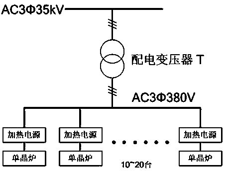
[0033] This embodiment also provides a new power distribution method on the basis of the above-mentioned power distribution system, as shown in the attached image 3 As shown, the three-phase 35kV high-voltage power from the power grid is connected to the 24-pulse rectification circuit 1, and the step-down rectification i...
PUM
 Abstract
Description
Claims
Application Information