Pulse time discrimination device

A pulse and time technology, applied in pulse description and other directions, can solve the problems of large measurement error, increase the complexity of the receiving system, and large measurement error, and achieve the effect of simple software and hardware processing, low cost, and good measurement accuracy.

Inactive Publication Date: 2014-01-22
BEIJING INSTITUTE OF PETROCHEMICAL TECHNOLOGY
View PDF2 Cites 3 Cited by
  • Summary
  • Abstract
  • Description
  • Claims
  • Application Information

AI Technical Summary

Problems solved by technology

[0002] The existing pulse time discrimination methods mainly include the frontier time discrimination method, the constant ratio discrimination method and the zero-crossing time discrimination method. The arrival time of the threshold point is used as the pulse characteristic time point, but this method is affected by the pulse amplitude swimming effect, and the measurement error is relatively large
The basic principle of the constant ratio screening method is to extract the moment when the half-high point of the rising edge of the pulse arrives as the characteristic time point of the pulse, but due to the influence of the wandering effect of the rising time of the pulse, there is still a large measurement error
The zero-crossing time discrimination method uses a high-pass capacitance-resistive filter to transform the unipolar pulse signal into a bipolar pulse signal, and uses the zero-crossing point of the bipolar pulse as the characteristic time point. After being amplified, it is shaped into a bipolar pulse by high-pass capacitance-resistive filtering. Although the timing error caused by the pulse amplitude change is very small, it is required to linearly amplify the signal without distortion. Therefore, automatic gain control is required for the signal, which increases the Receive system complexity and create additional timing errors

Method used


Image

  • Pulse time discrimination device
  • Pulse time discrimination device
  • Pulse time discrimination device

Examples


Embodiment Construction

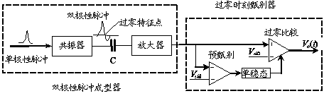
[0013] Depend on figure 1 As shown, a pulse time discrimination device is mainly composed of a bipolar pulse shaper and a double-threshold zero-crossing time discriminator, wherein the bipolar pulse shaper is composed of a pulse resonator and a pulse amplifier; the double-threshold zero-crossing time The discriminator is composed of zero-crossing comparator, pre-discriminator, monostable circuit and other parts. The unipolar pulse signal excites the pulse resonator to generate attenuation oscillation to form a bipolar pulse signal, and the zero-crossing time point of the bipolar pulse signal is used as the pulse time information. Among them, the pre-discriminator is to avoid false triggering of the zero-crossing comparator caused by noise or interference signal.

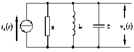
[0014] Depend on figure 2 An embodiment of the structure of the bipolar pulse shaper of the present invention is shown, which is composed of an oscillator and an AC amplifier composed of RLC parallel resonators. ...


PUM


Abstract

The invention discloses a pulse time discrimination device. The pulse time discrimination device comprises a bipolar pulse former and a double-threshold zero-passage time discriminator, which are connected with each other, wherein the bipolar pulse former consists of a pulse resonator and a pulse amplifier, which are connected in sequence; a unipolar pulse signal excites the pulse resonator to generate attenuation oscillation so as to form a bipolar pulse signal; by using a zero-passage time point of the bipolar pulse signal as pulse time information, the pulse amplifier only linearly amplifies an amplitude signal nearby a zero-passage point; the double-threshold zero-passage time discriminator comprises a zero-passage comparator, a pre-discriminator, a monostable circuit and the like, which are connected in sequence. The pulse time discrimination device is simple in structure, low in cost and convenient and reliable to use, and can be applied to pulse time discrimination of measuring instruments such as nuclear physics and high-precision laser pulse distance measuring instruments.

Description

technical field [0001] The invention relates to a pulse time discriminating device, in particular to a pulse time discriminating device for accurately measuring the pulse timing when the pulse amplitude varies greatly. Background technique [0002] The existing pulse time discrimination methods mainly include the frontier time discrimination method, the constant ratio discrimination method and the zero-crossing time discrimination method. The arrival time of the threshold point is taken as the pulse characteristic time point, but this method is affected by the wandering effect of the pulse amplitude, and the measurement error is relatively large. The basic principle of the constant ratio screening method is to extract the moment when the half-high point of the rising edge of the pulse arrives as the characteristic time point of the pulse. However, due to the impact of the wandering effect of the rising time of the pulse, there is still a large measurement error. The zero-cr...

Claims


Application Information

Patent Timeline
Patent Type & Authority Applications(China)
IPC IPC(8): H03K5/125
Inventor 黄民双
Owner BEIJING INSTITUTE OF PETROCHEMICAL TECHNOLOGY
Why Eureka
Try Eureka