Power line carrier coding modulation method

A technology of power line carrier and code modulation, which is applied in the field of communication to achieve the effect of improving transmission performance, power line code modulation method is stable and reliable, and easy to modulate

Active Publication Date: 2014-01-22
SHENZHEN FRIENDCOM TECH DEV
View PDF3 Cites 9 Cited by
  • Summary
  • Abstract
  • Description
  • Claims
  • Application Information

AI Technical Summary

Problems solved by technology

The following content will be added after the documents are confirmed

Method used


Image

  • Power line carrier coding modulation method
  • Power line carrier coding modulation method
  • Power line carrier coding modulation method

Examples


no. 2 example

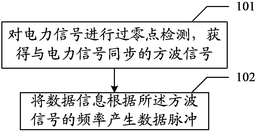
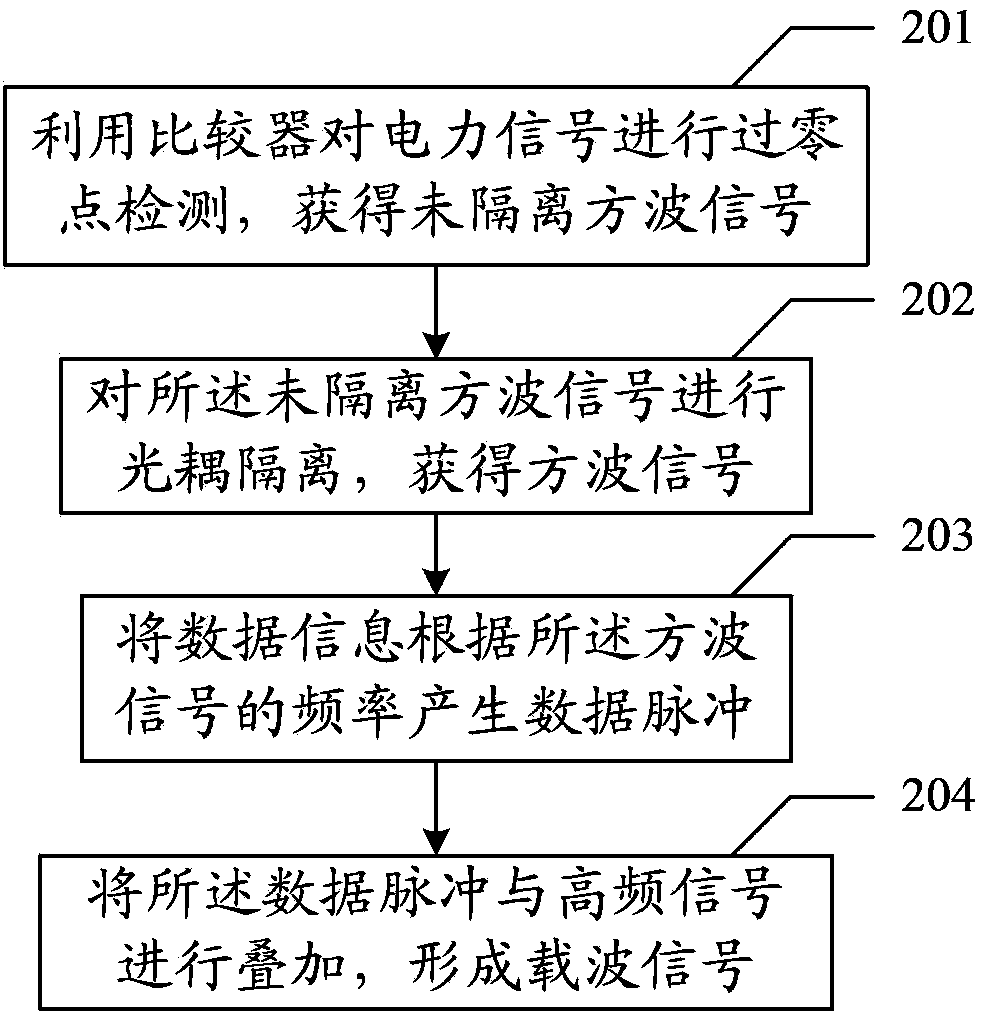
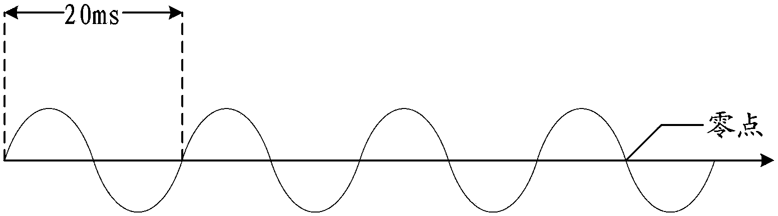
[0023] see figure 2 with image 3 , figure 2 It is a schematic diagram of the second embodiment of a power line carrier coding and modulation method in the embodiment of the present invention, image 3 is the power signal waveform diagram, Figure 4 is the synchronous signal waveform diagram, Figure 5 is the data pulse waveform diagram, Image 6 For the waveform diagram of the modulated carrier signal, the second embodiment of the power line carrier coding and modulation method includes:

[0024] 201. Using a comparator to detect the zero-crossing point of the power signal to obtain an unisolated synchronous signal;

[0025] The detection module uses a comparator to detect the zero-crossing point of the power signal to obtain an unisolated synchronous signal that is synchronized with the power signal. The waveform of the power signal is as follows image 3 As shown, specifically, the power signal is a sine wave voltage signal or current signal, and the period of the p...


PUM


Abstract

The embodiment of the invention discloses a power line carrier coding modulation method which is applicable to the technical field of communication. The power line carrier coding modulation method comprises the steps of: carrying out zero crossing point detection on an electric power signal; obtaining a synchronous signal which is synchronized with the electric power signal; and generating a data pulse of data information according to the frequency of the synchronous signal. The stability and reliability of the power line carrier coding modulation method are high.

Description

technical field [0001] The invention relates to the field of communication technology, in particular to a power line carrier code modulation method. Background technique [0002] Power line carrier communication technology refers to a technology that uses the power transmission line of the distribution network as a transmission medium to realize data transmission and information exchange. As a unique communication resource in the power sector, the power transmission line has high mechanical strength and is not easily damaged by external forces. Therefore, the power line carrier communication technology has the characteristics of simple networking, low cost, strong invulnerability, and easy implementation. It has developed rapidly in recent years. [0003] In the prior art, traditional coding and continuous modulation methods are used to code and modulate the carrier. However, due to the weak ability of traditional coding and continuous modulation to resist noise and adapt to...

Claims


Application Information

Patent Timeline
Patent Type & Authority Applications(China)
IPC IPC(8): H04B3/54
Inventor 崔涛吴金明刘文兵
Owner SHENZHEN FRIENDCOM TECH DEV
Why Eureka
Try Eureka