A kind of involute spline broach

A technology of involute splines and cutter teeth, which is applied in the direction of broaching tools, broaching machines, metal processing equipment, etc., can solve the problems of inability to guarantee dimensional accuracy requirements, spline strain, and tool stoppage, etc., and achieves obvious advantages in cost performance , high durability and small broaching deformation

Active Publication Date: 2016-01-06
EST TOOLS
View PDF6 Cites 1 Cited by
  • Summary
  • Abstract
  • Description
  • Claims
  • Application Information

AI Technical Summary

Problems solved by technology

However, there are many defects in the broach with full spiral tooth structure. On the one hand, because the broach is used for repeated grinding, the number of times of grinding is generally more than 10 times. The existence of the back angle of the tooth makes the diameter of the broach gradually gradually The reduction will directly affect the guarantee of the size and diameter of the spline of the part. In order to prevent the final diameter of the broach from changing greatly with the increase in the number of regrinding, the broach is designed with fine cutting teeth and calibration teeth. If the gradual transition is 0, there is a cylindrical margin increasing from 0.2 to 0.8 on the outer circle of the calibration tooth, and the clearance angle of the fine cutting tooth and the calibration tooth is smaller than that of the cutting tooth, and the broaches of the full spiral tooth structure type The back angle of the tooth is ground on the same helical line with one knife, which cannot guarantee the dimensional accuracy requirements of different tooth rises, land widths, and back angle angles. However, when grinding separately, there will be a standstill on the back angle surface, causing Edge defects lead to spline strain or rotten teeth; on the other hand, if the size and diameter of the spline of the part need to be adjusted, all the teeth of the broach need to be ground and modified synchronously, otherwise there will also be a tooth flank pick-up pause

Method used


Image

  • A kind of involute spline broach
  • A kind of involute spline broach
  • A kind of involute spline broach

Examples


Embodiment Construction

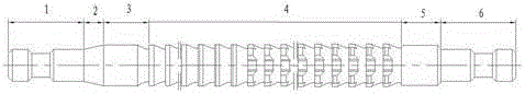
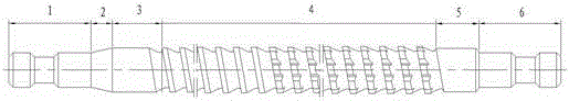
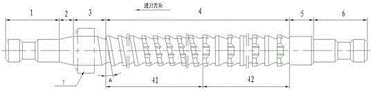
[0014] like image 3 As shown, the involute spline broach of the present invention includes a front handle 1, a transition cone 2, a front guide 3, a tooth portion 4, a rear guide 5 and a rear handle 6, wherein the tooth portion 4 includes a helical-toothed cutter segment 41 and an annular The tooth-shaped cutter segment 42 forms a combined tooth-shaped structure combining spiral and ring. The helical tooth segment 41 is arranged in the front section of the tooth part 4. It is a rough cutting tooth, which forms the effective tooth shape of the involute of the part, and bears most of the cutting amount and the effective tooth surface of the spline involute. Forming, the helix angle A, that is, the blade inclination angle, is controlled between 0°~20°, and the number of helix threads is selected from 2 to 8 according to the actual diameter of the broach and the helix angle requirements. In order to facilitate diameter measurement, an even number of heads is usually selected. nu...


PUM


Abstract

The invention discloses an involute spline broach. A tooth portion comprises a helical tooth type broach section and an annular tooth type broach section, and the helical tooth type broach section is located at the front end of the tooth portion and refers to rough cutting teeth; the annual tooth type broach section is located at the rear end of the tooth portion and refers to fine cutting teeth and calibrating teeth; a joint part of the two broach sections is disconnected in a supporting-channel mode. A combined tooth structure combining a helical tooth type with an annual tooth type is adopted in design and configuration of the broach teeth of the broach, so that cutting force is stable during operation, vibration of a machine tool is low, a broached part is small in deformation, spline precision is high, and broach manufacturing process is high, the involute spline broach is especially applicable to broaching processing of high-precision internal splines, especially splines with small effective length and thin-walled parts, such as a synchronizer gear sleeve and inner gear ring of an automobile.

Description

technical field [0001] The invention relates to a forming broaching tool, in particular to an involute spline broaching tool. Background technique [0002] In the field of mechanical processing, especially the cutting of involute internal splines, the broaching process is generally used. The formation of the involute tooth profile is formed by the passing diameters of dozens to hundreds of teeth distributed on the broach. It is formed incrementally tooth by tooth, so the structural type of the tooth arrangement of the broach is extremely important. The traditional broach adopts an annular tooth structure, that is, the front angle of each tooth of the broach is ring-shaped and independent, see figure 1 . The manufacturing process of this structure is simple, and the ordinary edge grinder can realize the grinding process, but during the broaching process, the circumferential cutting edge of each tooth is cut in and out synchronously, and the cutting is caused by the cyclic c...

Claims


Application Information

Patent Timeline
Patent Type & Authority Patents(China)
IPC IPC(8): B23D43/02
Inventor 陈子彦何勤松顾雪辉杨益波潘明峰
Owner EST TOOLS
Why Eureka
Try Eureka