Supercharge Your Innovation With Domain-Expert AI Agents!

Program control bottle machine

A bottle machine and control terminal technology, applied in the field of program-controlled bottle machines, can solve problems such as difficult production, complex overall structure, and low quality precision of bottle making

Active Publication Date: 2015-10-28
SHIJIAZHUANG LOYAL MACHINERY MFG
View PDF6 Cites 0 Cited by
  • Summary
  • Abstract
  • Description
  • Claims
  • Application Information

AI Technical Summary

Problems solved by technology

The control method of this kind of complete mechanical transmission has the following disadvantages: One: the adjustability of the above-mentioned mechanical components is poor
Since the above-mentioned drive control mechanisms all adopt the control mode of mechanical transmission, the A and B chuck disc indexing and station setting, the bottle body length fixing mechanism, the neck making mechanism, the chuck lifting opening and closing mechanism, and the bottle dropping mechanism are composed. The part is not adjustable, so the processing accuracy of the machine parts is high, especially the difficulty of assembly and debugging of the bottle making machine
Second: the drive positioning accuracy of each mechanical component is low
Since each drive control mechanism adopts the control mode of mechanical transmission, the driving and positioning accuracy of the bottle making machine revolution, rotation control, bottle length fixing mechanism, neck mechanism, clamp lifting opening and closing mechanism and bottle dropping mechanism is low, resulting in the overall The quality and precision of bottle making is not high
Third: the overall structure is complex, the processing of machine parts requires high precision, and manufacturing is difficult
Fourth: This kind of control method adopts mechanical transmission, which is not suitable for the needs of automatic program control of the bottle making machine

Method used


Image

  • Program control bottle machine
  • Program control bottle machine
  • Program control bottle machine

Examples


Embodiment Construction

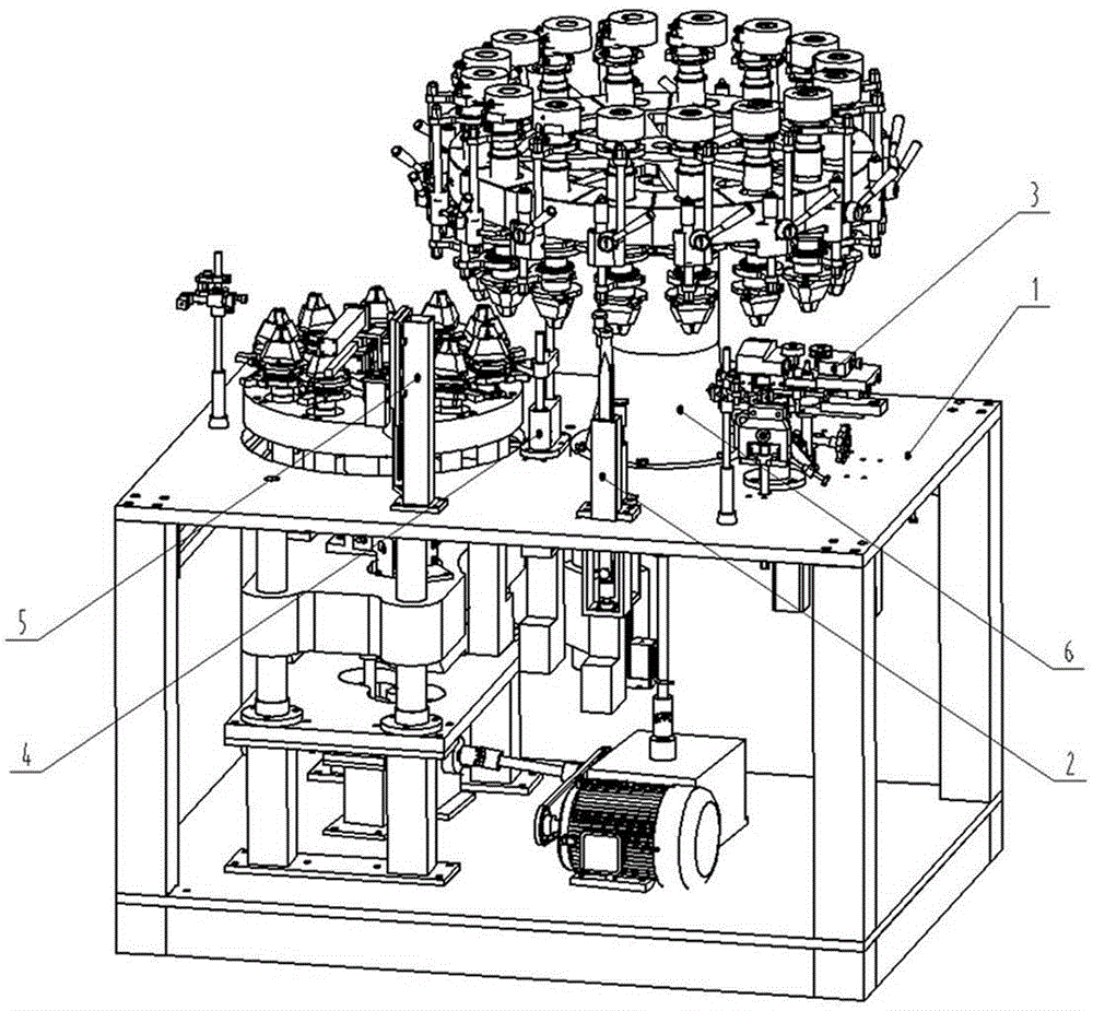
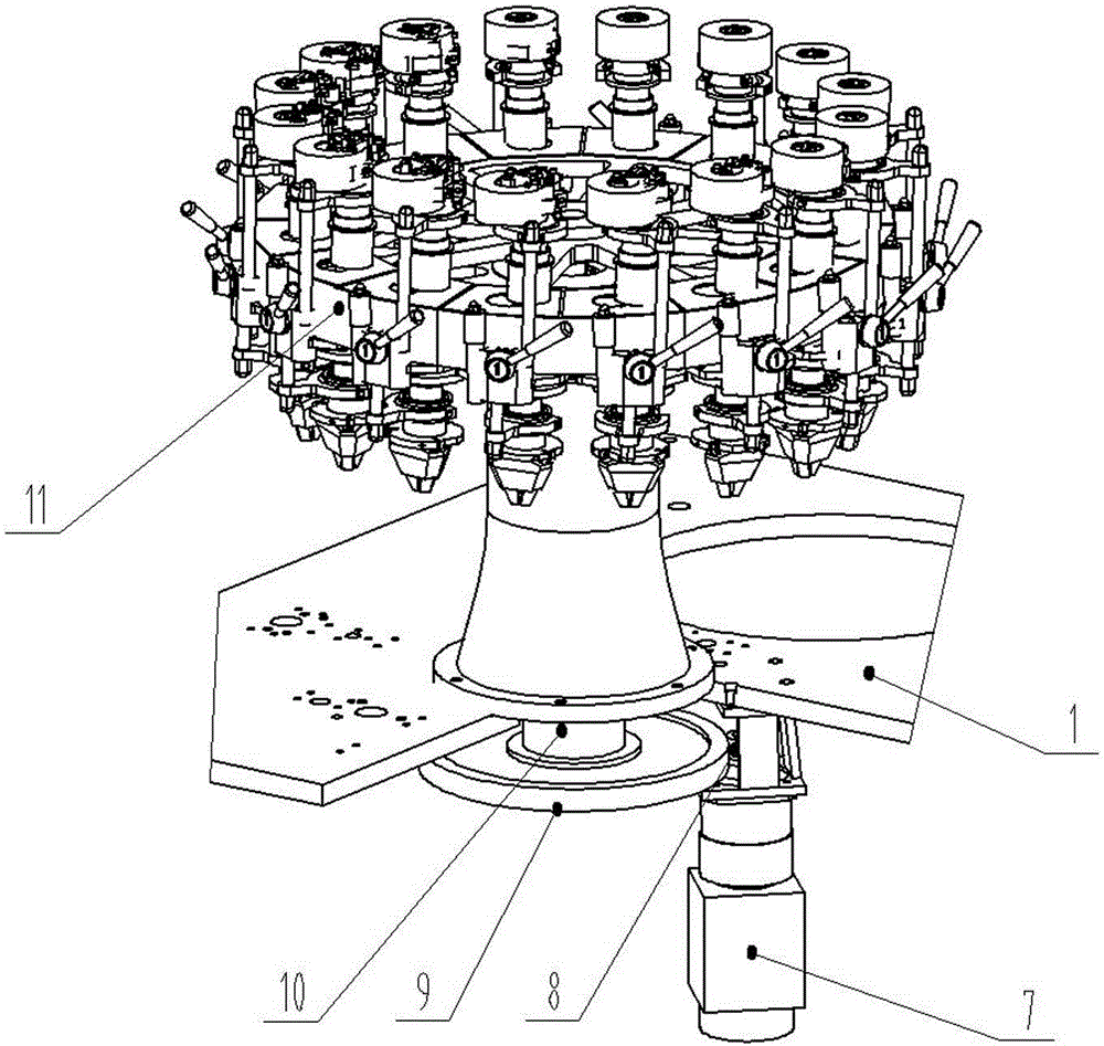
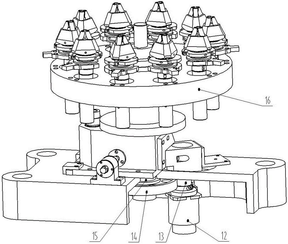
[0014] The present invention will be further described below with the accompanying drawings as examples. This process control bottle machine is an improved invention of the existing bottle making machine, such as figure 1As shown, the stroke control bottle machine includes A-part chuck assembly, bottle body length fixing mechanism 2, neck-making mechanism 3, B-part chuck assembly, and chuck lifting opening and closing mechanism respectively assembled on the body 1. 4. Bottle drop mechanism 5. Heating assembly, revolution drive assembly and rotation drive assembly assembled in the lower part of the fuselage; the chuck assembly of part A is assembled on the fuselage 1 through the support sleeve 6, and the bottle body is fixed in length The mechanism 2 and the neck mechanism 3 are respectively arranged on the fuselage 1 corresponding to the controlled chuck of the chuck assembly of part A; the chuck assembly of part B is arranged on the fuselage 1 on the side of the chuck assembl...


PUM


Abstract

The invention relates to a program control type bottle making machine which comprises a part A chuck assembly, a bottle body fixed length mechanism, a neck making mechanism, a part B chuck assembly, a chuck lifting and opening-closing mechanism, a bottle falling mechanism, a heating assembly, a revolution driving assembly and a rotation driving assembly, wherein the part A chuck assembly, the bottle body fixed length mechanism, the neck making mechanism, the part B chuck assembly, the chuck lifting and opening-closing mechanism, the bottle falling mechanism and the heating assembly are respectively correspondingly assembled on a machine body, and the revolution driving assembly and the rotation driving assembly are assembled at the lower part of the machine body. The program control type bottle making machine further comprises a controller used for controlling the revolution driving assembly, the rotation driving assembly and all control mechanisms, the output of the controller is respectively connected with the revolution driving assembly, the rotation drive assembly and the input control ends of controllers of the control mechanisms, the outputs of the revolution driving assembly and the rotation driving assembly are respectively connected with the revolution and rotation driving input control ends of the part A chuck assembly and the part B chuck assembly; the part B chuck assembly is independently assembled at one side of the part A chuck assembly, and an upper chuck and a lower chuck which are mutually joined between the part A chuck assembly and the part B chuck assembly axially correspond. According to the program control type bottle making machine, the high-precision matching among all the driving control mechanisms is improved, and the high-precision bottle making quality of the bottle making machine is ensured.

Description

technical field [0001] The invention relates to a program-controlled bottle machine. Background technique [0002] Most of the currently used bottle making machines are composed of A part chuck assembly, bottle body length fixing mechanism, neck making mechanism, B part chuck assembly, chuck lifting opening and closing mechanism, bottle dropping mechanism, The heating assembly is composed of a revolution drive assembly and an autorotation drive assembly assembled at the lower part of the fuselage; the chuck assembly of part A is assembled on the fuselage through a support sleeve, and the bottle body length fixing mechanism and the neck making mechanism are respectively arranged on the Corresponding to the fuselage of the chuck assembly of part A which is controlled by the chuck; the chuck assembly of part B is arranged on the fuselage on the side of the chuck assembly of part A, and the chuck assembly of part A and the chuck assembly of part B The upper and lower chucks tha...

Claims


Application Information

Patent Timeline
Patent Type & Authority Patents(China)
IPC IPC(8): C03B9/00
Inventor 张士华赵强刘新玺
Owner SHIJIAZHUANG LOYAL MACHINERY MFG
Features
  • R&D
  • Intellectual Property
  • Life Sciences
  • Materials
  • Tech Scout
  • Unparalleled Data Quality
  • Higher Quality Content
  • 60% Fewer Hallucinations
Learn More