Variable cross-section cantilever bridge box girder self-locking synchronization pushing system and construction method

A bridge box girder and variable cross-section technology, which is applied to bridges, bridge construction, erection/assembly of bridges, etc., can solve the problems of inflexible arrangement of sliding bearings, low reuse rate, and increased cost

Active Publication Date: 2014-01-29
EAST STEEL STRUCTURE BRIDGE
View PDF8 Cites 29 Cited by
  • Summary
  • Abstract
  • Description
  • Claims
  • Application Information

AI Technical Summary

Problems solved by technology

[0004]1. The traction force cannot be counteracted by itself, and will act horizontally along the bridge direction on the temporary independent supports and bridge piers;
[0005]2. The bottom plate of the bridge box girder slides on the fixed-height sliding bearing. The bottom surface of the bridge is not flat due to the camber, and the sliding bearing cannot To adapt to the constantly changing elevation of the bridge bottom;
[0006]3. The sliding bearing cannot limit the lateral position of the bridge body, and a lateral jack is required to

Method used


Image

  • Variable cross-section cantilever bridge box girder self-locking synchronization pushing system and construction method
  • Variable cross-section cantilever bridge box girder self-locking synchronization pushing system and construction method
  • Variable cross-section cantilever bridge box girder self-locking synchronization pushing system and construction method

Examples


Embodiment Construction

[0046] The present invention will be further described below in conjunction with the accompanying drawings.

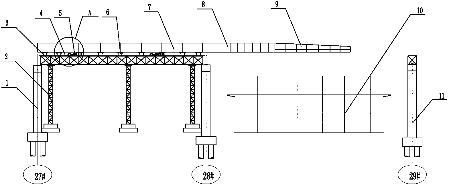
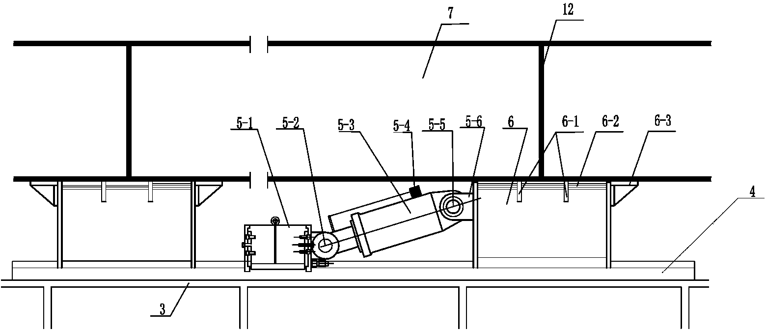
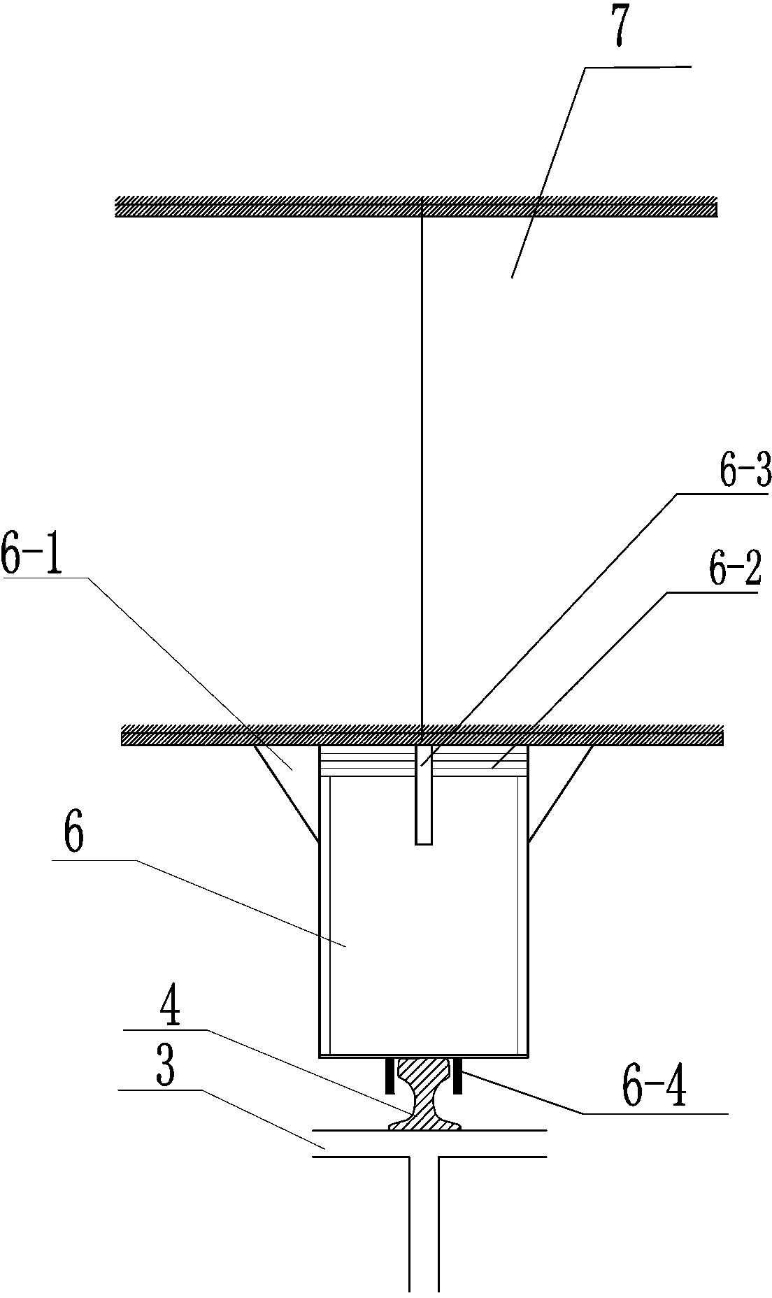
[0047] Such as Figure 1-4 As shown, the variable cross-section cantilever bridge box girder self-locking synchronous jacking system of the present invention includes a push-sliding bridge box girder welding and assembly platform system arranged on one side of the cross-railway, and the push-sliding bridge box girder welding and assembling platform The system consists of a temporary support pier 2, a push-slip bridge box girder welding assembly platform 3 arranged on the temporary support pier 2, and a sliding track 4 arranged on the push-slide bridge box girder welding assembly platform 3. Composition, a set of sliding shoes 6 and a set of self-locking synchronous pushing devices 5 are installed on the sliding track 4, and the set of self-locking synchronous pushing devices 5 are electrically connected with the automatic control system of pushing, which Features:

...


PUM


Abstract

The invention relates to a variable cross-section cantilever bridge box girder self-locking synchronization pushing system and a construction method. The variable cross-section cantilever bridge box girder self-locking synchronization pushing system comprises a pushing sliding bridge box girder welding assembling platform system, sliding tracks, a group of sliding shoes and a group of self-locking synchronization pushing devices, wherein the group of sliding shoes and the group of self-locking synchronization pushing devices are installed on the sliding tracks, and pushing is automatically controlled. The variable cross-section cantilever bridge box girder self-locking synchronization pushing system is characterized in that every self-locking synchronization pushing device comprises a hydraulic pushing oil cylinder and a self-locking pushing rail clamping device, adjusting pad blocks for adjusting bridge type camber are arranged on the upper portions of the sliding shoes, and thrust plates and side limiting plates, which are used for preventing the sliding shoes from jumping during pushing, are respectively arranged in front of and on the sides of the sliding shoes. Track limiting plates for limiting sliding shoe offset are arranged on two sides of the parts on the lower portions of the sliding shoes contacted with the tracks, a bridge box girder is placed on the upper portions of the sliding shoes, and a bridge box girder transition section and a guide beam are arranged at the front end of the first section of bridge box girder. By adopting the variable cross-section cantilever bridge box girder self-locking synchronization pushing system construction method, the problem of difficulty in bridge erection in complex environments of crossing railways and the like is effectively solved, and the variable cross-section cantilever bridge box girder self-locking synchronization pushing system is safe, reliable and high in efficiency.

Description

Technical field [0001] The present invention involves a bridge box beam construction equipment and its bridge box construction method, especially a self -locking system and construction method of a variable -section cantilever bridge box beam. Background technique [0002] The construction of the rapid interoperability of China's cities is being fully launched. Due to its light structure, high strength, fast installation, and diverse shapes, steel structure bridges have been widely used in large -scale bridges at home and abroad.Most of the temporary bracket installation methods are adopted during the bridge installation. Due to the normal operation of the trains, the cross -rail bridge cannot support the installation of the fetal frame. It can only be installed in the sliding method.The traction of this scheme should be transmitted to temporary pillars and bridge pier through the reaction device to increase the temporary pillar and basic design dimensions, and at the same time, ...

Claims


Application Information

Patent Timeline
IPC IPC(8): E01D21/06
Inventor 郑永会孙宇凡尚瞳
Owner EAST STEEL STRUCTURE BRIDGE
Why Eureka
Try Eureka