Ku-band circularly polarized dielectric resonator antenna

A dielectric resonator and Ku-band technology, applied in the field of Ku-band circularly polarized dielectric resonator antennas, can solve the problems of high antenna cost, large volume, inconvenient use, etc., and achieve the effect of small antenna size

Inactive Publication Date: 2014-01-29
SHANGHAI UNIV
View PDF1 Cites 24 Cited by
  • Summary
  • Abstract
  • Description
  • Claims
  • Application Information

AI Technical Summary

Problems solved by technology

This antenna has high application value, but this antenna has high cost and la

Method used


Image

  • Ku-band circularly polarized dielectric resonator antenna
  • Ku-band circularly polarized dielectric resonator antenna
  • Ku-band circularly polarized dielectric resonator antenna

Examples


Embodiment 1

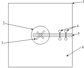
[0023] see Figure 1~Figure 3 , the Ku-band circularly polarized dielectric resonator antenna includes a layer of gold on the upper surface of the dielectric substrate (1)

[0024] It belongs to the ground plate (6) and a microstrip feeder (5) on the lower surface of the dielectric substrate (1), and is characterized in that:

[0025] 1) There is a three-layer stacked dielectric resonator (2) at the center above the metal ground plate (6);

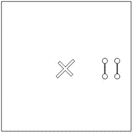
[0026] 2) There is a cross gap (3) at the center of the metal grounding plate (6);

[0027] 3) The inner end of the microstrip feeder (5) is directly below the cross slit (3), and the microstrip feeder and the cross slit (3) are at an angle of 45°;

[0028] 4) There are two cascaded dumbbell-shaped slots (4) on the metal ground plate (6) to widen the impedance bandwidth of the antenna.

Embodiment 2

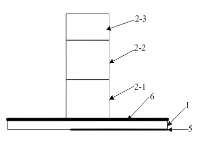
[0030] This embodiment is basically the same as Embodiment 1, and the special feature is: the three-layer stacked dielectric resonator (2) is a lower dielectric cylinder (2-1), a middle dielectric cylinder (2-2) and an upper dielectric cylinder ( 2-3) Stacked, three layers of dielectric cylinders have the same radius, different materials and heights, the main effect of their height and the dielectric constant of the material on the antenna is the resonant frequency of the antenna, and its size affects the axial ratio bandwidth of the antenna Greater impact. The three-layer stacked circularly polarized dielectric resonator (2) is coupled and fed by the microstrip feeder (5) through the cross gap (3) in the center of the metal ground plate (6); the length of the two arms of the cross gap (3) Not equal, equal width. Left-handed or right-handed circular polarization is realized by controlling the length of the two slits. The smaller the width of the dumbbell handle of the dumbbe...

Embodiment 3

[0032] This embodiment is basically the same as Embodiment 1, and the special features are as follows:

[0033] 1. The structure of the antenna is as follows: Figure 1-2 As shown, the lower layer is the microstrip feeder (5), the middle layer is the dielectric substrate (1), and the microstrip feeder with a characteristic impedance of 50 ohms is etched on the dielectric substrate layer; the upper layer is the ground plate (6), the cross slit (3) and The dumbbell-shaped slots (4) are all slotted on the grounding plate (6); the lower medium cylinder (2-1); the middle medium cylinder (2-2); the upper medium cylinder (2-3).

[0034] 2. Three-layer stacked dielectric resonators (3) have the same dielectric radius but different materials and heights. Their height and dielectric constant mainly affect the resonant frequency of the antenna, and their size has a great influence on the axial ratio bandwidth of the antenna.

[0035] 3. The ground plate (6) and the microstrip feeder (5...


PUM

PropertyMeasurementUnit
Axial ratioaaaaaaaaaa

Abstract

The invention relates to a Ku-band circularly polarized dielectric resonator antenna which comprises a metal grounding plate and a micro-strip feeder line. The metal grounding plate is arranged on the upper surface of a dielectric substrate, and the feeder line is arranged on the lower surface of the dielectric substrate. A three-tier dielectric resonator is arranged at the center of the upper surface of the metal grounding plate; a crisscrossed gap is formed in the center of the metal grounding plate; the inner end of the micro-strip feeder line is arranged right below the crisscrossed gap and forms a 45-degree angle with the same; two cascade-connection dumbbell-shaped groove gaps are formed in the grounding plate. Impedance bandwidth of the antenna is 27.67%, circularly polarized axial ratio bandwidth 6.56%. within working frequency, the maximum gain of the antenna is 8.2dB, the minimum gain is 6.0dB, and the antenna has wider coverage range. Axial ratio of the 12.2GHz position is approximately 0.09dB, and the antenna has good circularly polarized characteristics. The antenna covers commonly used working frequency bands of satellite television broadcasting in IT3, and is applicable to a satellite television broadcasting system within 11-14.5GHz frequency bands.

Description

technical field [0001] The invention relates to a Ku-band circularly polarized dielectric resonator antenna. The antenna works in the Ku band, the impedance bandwidth is 27.67%, the circular polarization axis ratio bandwidth is 6.56%, the gain is 6.0dB-8.2 dB, and the directivity is relatively good. The antenna covers the common working frequency band of satellite TV broadcasting in IT3 area, so it can be applied to the satellite TV broadcasting system in the frequency band of 11GHz-14.5GHz. Background technique [0002] With the development of modern wireless communication technology and the popularization of wireless application products, people put forward higher requirements for antennas that are indispensable for wireless communication systems, such as good circular polarization characteristics, high gain, small size and light weight. It has a high transmission rate, suppresses rain and fog interference and anti-multipath reflection, etc. Especially in satellite commu...

Claims


Application Information

Patent Timeline
IPC IPC(8): H01Q1/36H01Q1/48H01Q1/50
Inventor 沈文辉刘洁刘丹张钰
Owner SHANGHAI UNIV
Why Eureka
Try Eureka