Eureka AIR delivers breakthrough ideas for toughest innovation challenges, trusted by R&D personnel around the world.

Oven controlled crystal oscillator

一种恒温槽、振荡器的技术,应用在输出稳定、电气元件等方向,能够解决水晶振子安装位置偏离、温度稳定性不够充分、难以降低高度方向的尺寸等问题,达到实现低背化、提高热响应性及温度稳定性、温度特性优异的效果

Active Publication Date: 2014-01-29
NIHON DEMPA KOGYO CO LTD
View PDF20 Cites 6 Cited by
  • Summary
  • Abstract
  • Description
  • Claims
  • Application Information

AI Technical Summary

Problems solved by technology

[0046] However, in the conventional crystal oscillator with a constant temperature bath, it is difficult to reduce the size in the height direction if the heat cylinder is used, and there is a problem that the temperature stability is insufficient if the heat cylinder is not used.
[0047] Moreover, in the conventional crystal oscillator with a constant temperature bath using a cylindrical crystal oscillator, there is a problem that heat cannot be efficiently conducted, and the temperature stability is low.
[0048] Furthermore, if the crystal vibrator is directly soldered (reflow mounted) to the substrate without using a heat cylinder, the profile can be reduced, but when reflow mounting a lead type (lead type) crystal vibrator, the solder will Flow, so there is a problem that the installation position of the crystal oscillator deviates

Method used


Image

  • Oven controlled crystal oscillator
  • Oven controlled crystal oscillator
  • Oven controlled crystal oscillator

Examples


no. 1 Embodiment approach

[0096] [First embodiment: FIG. 1(a), FIG. 1(b)]

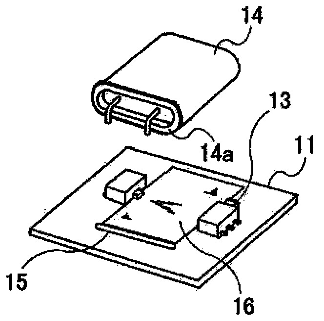
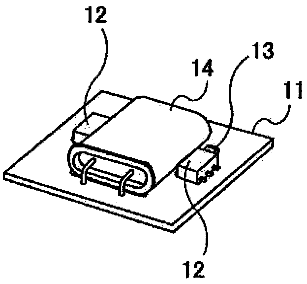
[0097] The structure of the crystal oscillator with a constant temperature bath according to the first embodiment of the present invention will be described using FIG. 1( a ) and FIG. 1( b ). Fig. 1 (a) and Fig. 1 (b) are schematic explanatory views showing the structure of an oscillator used in a crystal oscillator with a constant temperature bath according to the first embodiment of the present invention, and Fig. 1 (a) is an exploded explanatory view, Figure 1(b) is an explanatory diagram of the appearance.

[0098] As shown in Fig. 1 (a) and Fig. 1 (b), the oscillator of the crystal oscillator with constant temperature tank (the first crystal oscillator with constant temperature tank) of the first embodiment of the present invention is as follows: On one surface of the circuit board 11 , a heat source 12 , a thermistor 13 , and a crystal oscillator 14 are provided.

[0099] That is, the first crystal oscillator with const...

no. 2 Embodiment approach

[0172] [Second embodiment: FIG. 3(a), FIG. 3(b)]

[0173] Next, the configuration of a crystal oscillator with a constant temperature bath according to a second embodiment of the present invention will be described using FIG. 3( a ) and FIG. 3( b ). Fig. 3 (a) and Fig. 3 (b) are schematic explanatory diagrams showing the structure of an oscillator used in a crystal oscillator with a constant temperature bath according to a second embodiment of the present invention, and Fig. 3 (a) is an appearance explanatory diagram, Fig. 3(b) is a partial explanatory diagram.

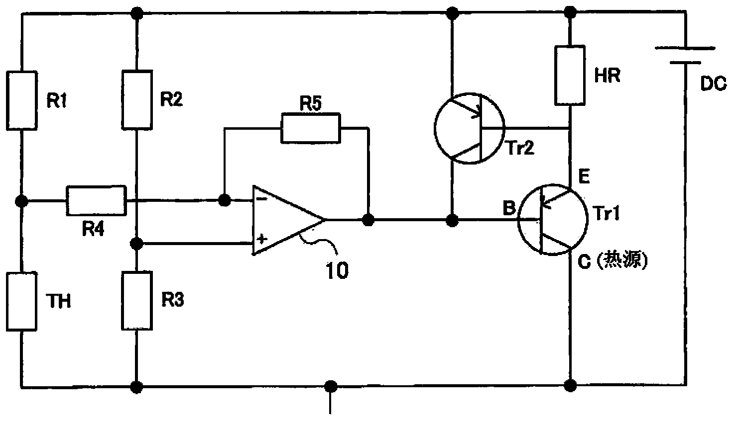
[0174] A crystal oscillator with a constant temperature bath (a second crystal oscillator with a constant temperature bath) according to a second embodiment of the present invention includes: a cylindrical crystal oscillator shown in FIGS. 6( a ) and 6 ( b ), and figure 2 The temperature control circuit shown.

[0175] As described above, the cylindrical crystal resonator has long-term stable frequency characterist...


PUM


Abstract

An oven controlled crystal oscillator includes a crystal unit, a temperature control circuit, and a circuit board. The temperature control circuit is configured to control a temperature of the crystal unit. The crystal unit includes a flange that projects outward to an entire outer periphery in one end. The circuit board includes a depressed portion in which the flange is partially inserted. The temperature control circuit includes a power transistor, a thermistor as a temperature sensor, and a metal pattern. The power transistor becomes a heat source. The metal pattern commonly connects a ground terminal of the crystal unit, a collector of the power transistor, and a ground terminal of the thermistor. The crystal unit is positioned in a state where the flange is partially inserted in the depressed portion. The crystal unit is connected to the metal pattern.

Description

technical field [0001] The present invention relates to a crystal oscillator (Oven Controlled Crystal Oscillator, OCXO) with a constant temperature tank, in particular to a crystal oscillator that can realize low profile and improve temperature stability, and then install the crystal oscillator on the Crystal oscillator with constant temperature bath at specified position. Background technique [0002] [Description of prior art: FIG. 4(a), FIG. 4(b)] [0003] The crystal oscillator with constant temperature bath maintains the operating temperature of the crystal oscillator at a constant level, so it does not cause frequency changes depending on the frequency-temperature characteristic, and can obtain a highly stable oscillation frequency. [0004] A conventional crystal oscillator with a constant temperature bath will be described using FIG. 4( a ) and FIG. 4( b ). Fig. 4 (a), Fig. 4 (b) are the schematic explanatory diagrams showing the structure of the oscillator used in...

Claims


Application Information

Patent Timeline
Patent Type & Authority Applications(China)
IPC IPC(8): H03L1/04
CPCH03L1/04
Inventor 吉村崇弘新井淳一
Owner NIHON DEMPA KOGYO CO LTD
Why Eureka
Eureka Blog
Learn More