Supercharge Your Innovation With Domain-Expert AI Agents!

Improvements regarding waste disposal

A technology for treating chambers and municipal solid waste, which is applied in the fields of solid waste removal, pyrolysis treatment of sludge, and biomass drying, etc., and can solve the problems of reducing the heat transfer efficiency of materials

Inactive Publication Date: 2016-04-06
CHINOOK END STAGE RECYCLING
View PDF7 Cites 0 Cited by
  • Summary
  • Abstract
  • Description
  • Claims
  • Application Information

AI Technical Summary

Problems solved by technology

Also, as mentioned above, because the material in the furnace tends to undergo bulk motion, only a small portion of the interior walls are in contact with the waste material at any one time, reducing the efficiency of heat transfer to the material that has moved

Method used


Image

  • Improvements regarding waste disposal
  • Improvements regarding waste disposal
  • Improvements regarding waste disposal

Examples


Embodiment Construction

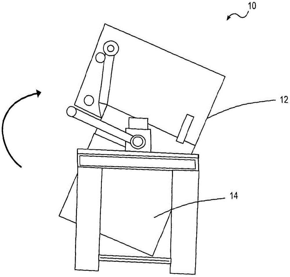
[0029] see figure 1 , shows a rotary furnace. The furnace 10 includes a processing chamber 12 and a charging box 14 connected to the processing chamber and allowing waste to be added to and removed from the furnace. The basic principles of the furnace's operation can be found in prior art document WO2004 / 059229. The waste to be processed is loaded into a charging box which is then connected to the rotary kiln. As the material within the furnace is heated, the furnace rotates to decompose the material. The material may be heated in an atmosphere of zero or approximately zero percent oxygen such that the material pyrolyzes in the furnace to produce gas.

[0030] Although the prior art is described as having an integral afterburner for combusting the gases being produced, it will be appreciated that the afterburner may be separate from the furnace and connected to it by piping. Those skilled in the art will appreciate that an afterburner may be used to combust gases produced ...


PUM


Abstract

The invention provides an apparatus for treating material (29) such as organic coating waste and organic material including biological material, industrial waste, municipal solid waste and sludge. The apparatus includes a furnace having a rotatable portion including a processing chamber adapted to contain material for processing. A plurality of gas inlets are provided in at least one wall of the processing chamber through which hot gases are introduced into the processing chamber to heat a material within the processing chamber, thereby pyrolyzing an organic component of the material or gasification. At least one deceleration device (26) is located in the processing chamber to decelerate the movement of waste material within the furnace as the furnace rotates.

Description

technical field [0001] The present invention relates to improvements in the processing of materials with organic constituents. In particular, it relates to improvements in methods of processing such materials in rotary furnaces. Background technique [0002] The use of large rotary kilns for waste treatment is known in the art. Examples of rotary furnaces for this purpose can be found, for example, in PCT publication WO 2004 / 059229. This document discloses a rotary furnace for treating waste, said rotary furnace having a plurality of nozzles to eliminate the entry of heated gases into its treatment chamber. Although only a single row of inlets is shown in this prior art document, in practice an array of inlets covering the sides of the process chamber or at least one side of the process chamber may be provided. [0003] As the rotary kiln rotates, waste material within the rotary kiln will fall onto the inlet, temporarily blocking said inlet and reducing air flow through ...

Claims


Application Information

Patent Timeline
Patent Type & Authority Patents(China)
IPC IPC(8): F23G5/20
CPCC02F11/10F23G5/0273F23G2203/201F23G2203/204F23G2203/208F26B11/02F26B25/04F26B25/12F26B2200/02F26B2200/18Y02W10/40F23G5/20B09B3/00F26B11/028
Inventor 瑞法特·阿尔·沙拉比奥菲尼尔·亨利·佩里约翰·特纳
Owner CHINOOK END STAGE RECYCLING
Features
  • R&D
  • Intellectual Property
  • Life Sciences
  • Materials
  • Tech Scout
  • Unparalleled Data Quality
  • Higher Quality Content
  • 60% Fewer Hallucinations
Learn More