
A brushless motor with automatic temperature adjustment function

An automatic adjustment, brushless motor technology, applied in the direction of motor control, electrical components, control systems, etc., can solve the problems of unconsidered chips, damaged parts, high integration, and achieve the effect of simple structure and low manufacturing cost

Active Publication Date: 2016-08-03
ZHONGSHAN BROAD OCEAN
View PDF4 Cites 1 Cited by
  • Summary
  • Abstract
  • Description
  • Claims
  • Application Information

AI Technical Summary

Problems solved by technology

[0002] At present, the DC brushless motor controller generally has a microprocessor MCU and an IGBT driver chip. The combination of the microprocessor MCU and the IGBT driver chip has complex peripheral circuits, which leads to increased costs and does not fully utilize the microprocessor MCU. In view of this, some manufacturers have specially developed dedicated integrated chips for DC brushless motors - motor intelligent power chips, such as the TPD4122K motor control chip developed by Toshiba, and the FM5001 and AX02 chips developed by other companies. High, the peripheral circuit is small, the circuit structure is simple, the cost is low, so it is accepted by the majority of manufacturers
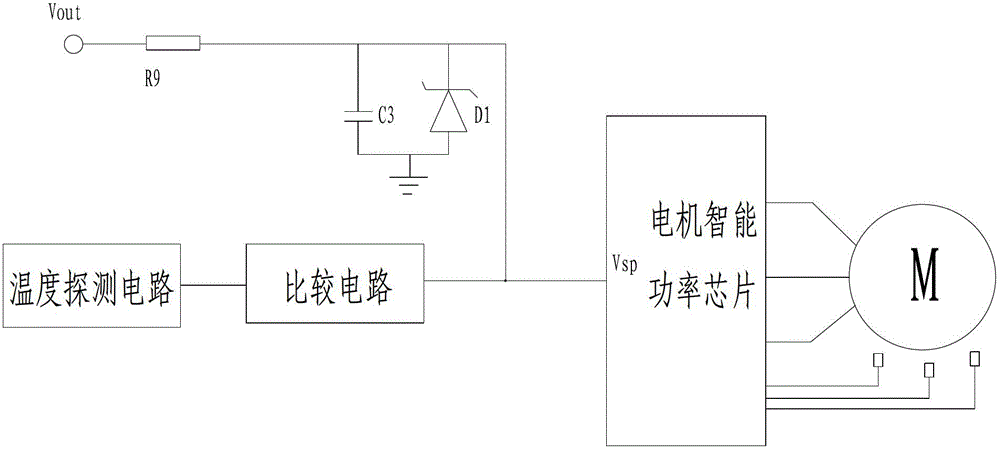
However, there are also some defects: since the pins of each chip are defined, some chips have not been considered in the development, lack of temperature protection function, and the motor control chip is difficult to dissipate quickly due to the large amount of heat during work, so it often burns out The phenomenon
But this approach has certain problems: Some air conditioner users find that when the temperature of the whole unit is too high, if the fan motor stops due to temperature protection, it will damage many parts of the entire air conditioner and affect the indoor cooling effect.

Method used


Image

  • A brushless motor with automatic temperature adjustment function
  • A brushless motor with automatic temperature adjustment function
  • A brushless motor with automatic temperature adjustment function

Examples


Embodiment Construction

[0023] Below by specific embodiment and in conjunction with accompanying drawing, the present invention is described in further detail:

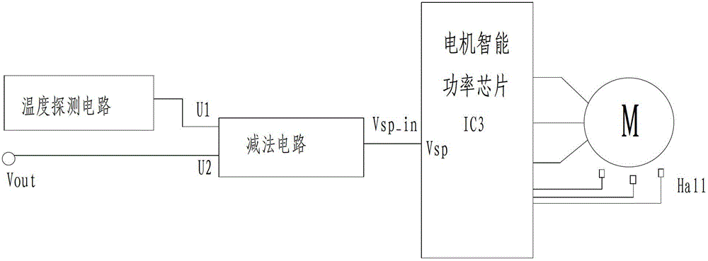
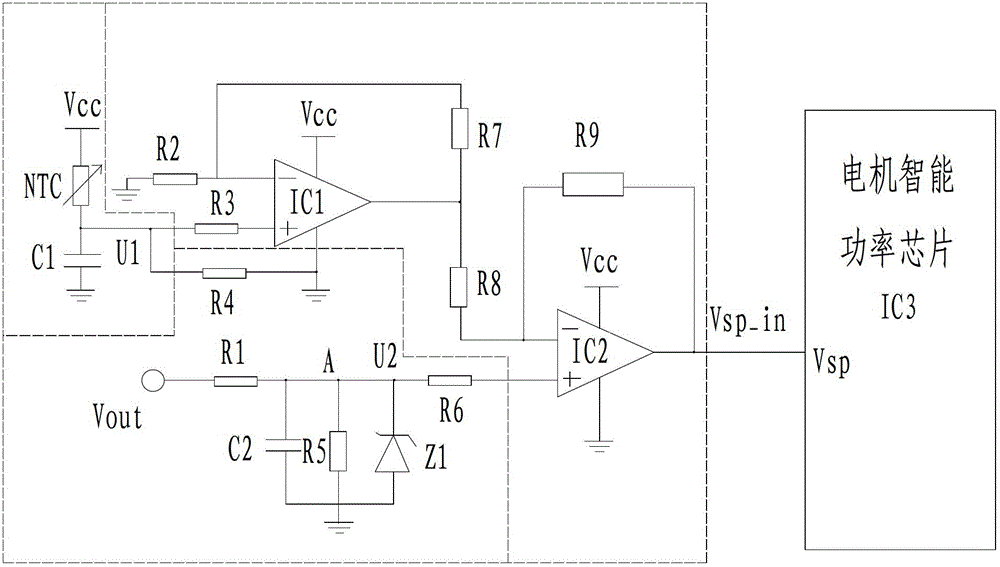
[0024] Such as figure 2 , image 3 As shown, a brushless motor with temperature automatic adjustment function includes motor intelligent power chip IC3, which is provided with a speed signal input port Vsp, and it also includes a temperature detection circuit and a subtraction circuit, and the temperature detection circuit detects The temperature signal of the motor intelligent power chip IC3 is converted into a voltage signal U1 and input to one input terminal of the subtraction circuit, the external system control signal Vout is converted into a voltage signal U2 and input to the other input terminal of the subtraction circuit, and the output terminal Vsp_in of the subtraction circuit is connected to The speed signal input port Vsp set by the motor intelligent power chip IC3, the temperature detection circuit includes the temperature sen...


PUM


Abstract

The invention relates to a brushless motor with automatic temperature adjustment function, comprising a motor intelligent power chip IC3, the motor intelligent power chip IC3 is provided with a speed signal input port Vsp, and is characterized in that it also includes a temperature detection circuit and a subtraction circuit, the temperature The detection circuit detects the temperature signal of the motor intelligent power chip IC3 and converts it into a voltage signal U1, which is input to one input terminal of the subtraction circuit, and the external system control signal Vout is converted into a voltage signal U2, which is input to the other input terminal of the subtraction circuit, and the output of the subtraction circuit The end Vsp_in is connected to the speed signal input port Vsp set by the motor intelligent power chip IC3. When the temperature of the motor rises to a certain level, the resistance value of the temperature-sensitive resistor NTC decreases sharply, so that the input voltage of the speed signal input port Vsp decreases, and the motor speed will automatically decrease, but the motor will not stop. Automatic drop, so this greatly improves the reliability of the motor and meets the customer's technical requirements - high temperature does not stop, effectively protecting the parts of the user's complete machine.

Description

Technical field: [0001] The invention relates to a brushless motor with automatic temperature adjustment function. Background technique: [0002] At present, the DC brushless motor controller generally has a microprocessor MCU and an IGBT driver chip. The combination of the microprocessor MCU and the IGBT driver chip has complex peripheral circuits, which leads to increased costs and does not fully utilize the microprocessor MCU. In view of this, some manufacturers have specially developed dedicated integrated chips for DC brushless motors - motor intelligent power chips, such as the TPD4122K motor control chip developed by Toshiba, and the FM5001 and AX02 chips developed by other companies. High, small peripheral circuit, simple circuit structure, and low cost, so it is accepted by the majority of manufacturers. However, there are also some defects: since the pins of each chip are defined, some chips have not been considered in the development, lack of temperature protecti...

Claims


Application Information

Patent Timeline
IPC IPC(8): H02P29/60H02P29/68
CPCH02P29/68H02P29/60
Inventor 孙海荣
Owner ZHONGSHAN BROAD OCEAN
Learn More