Vacuum compression moulding machine

A vacuum pressure and forming machine technology, applied in the field of pressure forming machines, can solve the problems of mold deformation, high manufacturing cost, high use cost and energy consumption cost, product size impact, etc. occupied effect

Inactive Publication Date: 2014-02-05
叶渊理 +1
View PDF4 Cites 2 Cited by
  • Summary
  • Abstract
  • Description
  • Claims
  • Application Information

AI Technical Summary

Problems solved by technology

At the same time, the enlargement of the mold makes the periphery of the mold more and more away from the peripheral part of the hydraulic system plunger (ejector) that has the most clamping pressure on the mold for this type of equipment, which is very likely to make the periphery far away from the force center of the mold Slight deformation of the mold due to uneven force during work
If the mold is deformed, there will be a gap between the upper and lower molds, and the burrs or flashes

Method used


Image

  • Vacuum compression moulding machine
  • Vacuum compression moulding machine
  • Vacuum compression moulding machine

Examples


Example Embodiment

[0023] In order to make it easy to understand the technical means, creative features, objectives and effects achieved by the present invention, the present invention will be further explained below in conjunction with specific drawings.

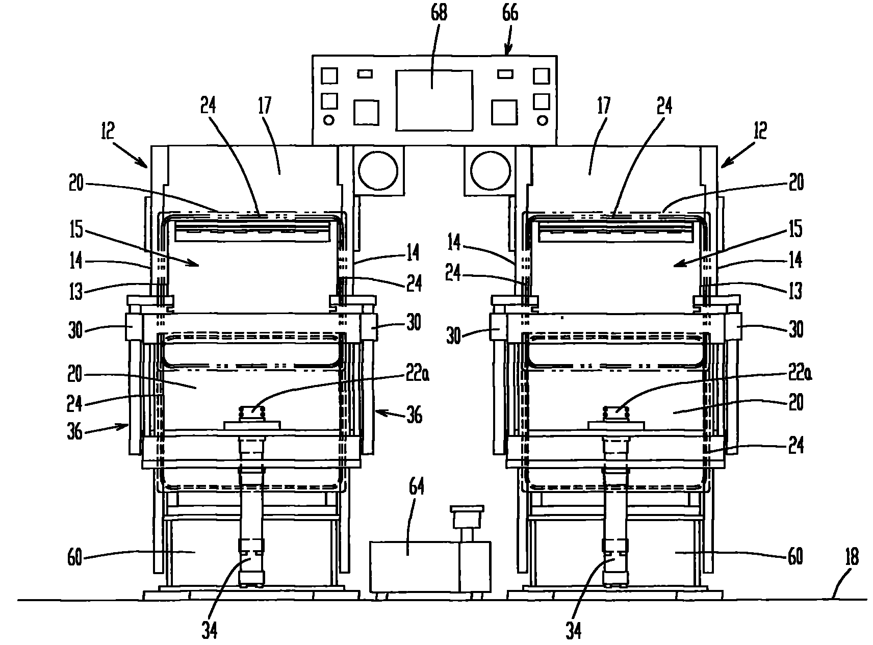
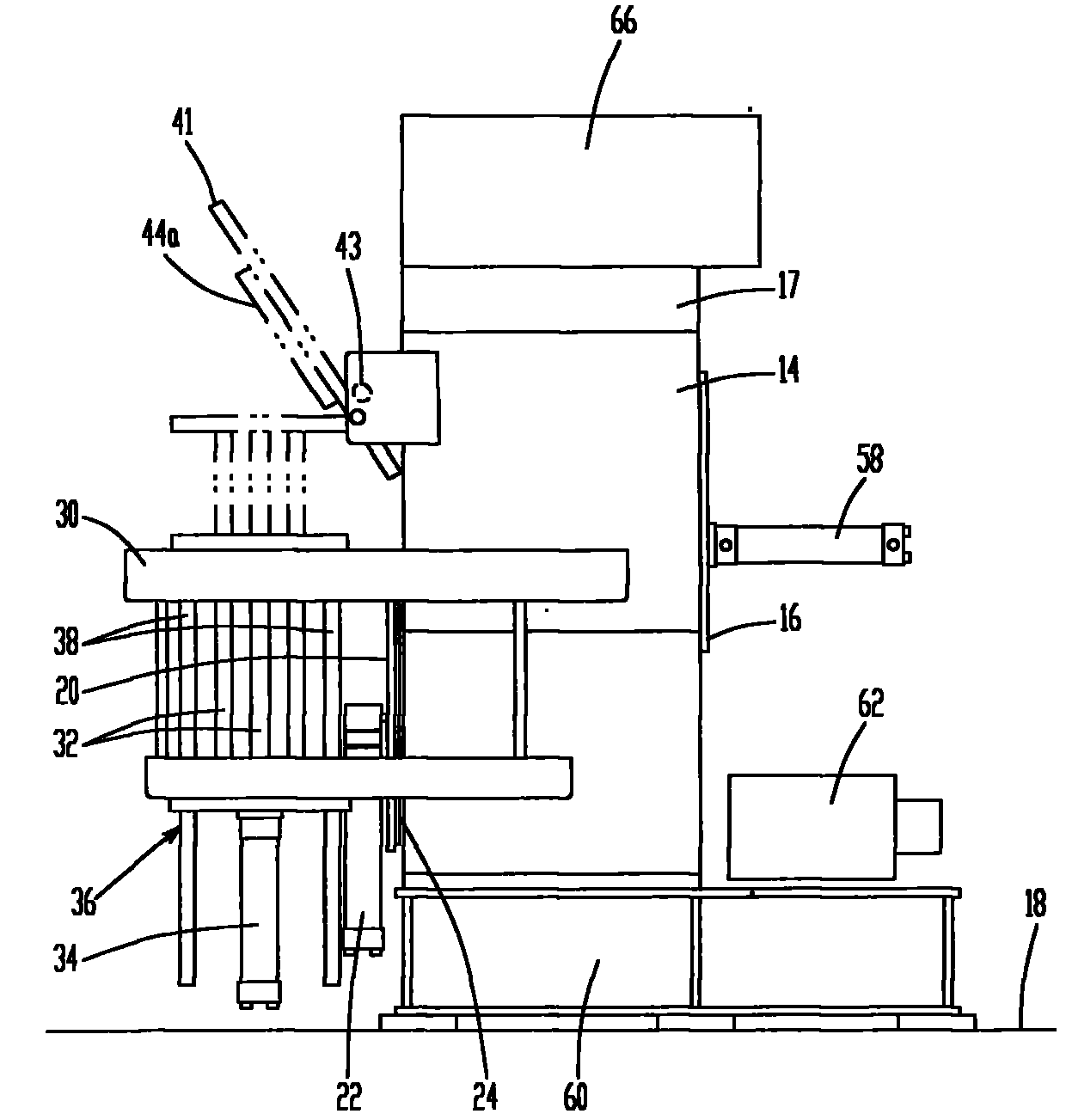
[0024] The following is a schematic illustration of this design embodiment. Figure 1-Figure 4 It represents an implementation form of this design. The vacuum pressure forming machine of this embodiment has two mainframes 12 in one group. The mainframe 12 shown in the figure is in the shape of a hexahedron. Of course, the mainframe 12 can also be processed into other shapes as required. Each device host 12 is composed of a pair of side plates 14 and a top plate 17 formed on a rectangular parallelepiped arranged on the bottom plate 18. A rectangular opening 13 is provided on the front of the main body 12 of the equipment, which communicates with the vacuum chamber 15 as a molding space in the main body 12. The vacuum chamber 15 of the equipment...


PUM


Abstract

The utility model relates to a vacuum compression moulding machine which comprises a main machine. The main machine comprises a vacuum chamber, a piston, a hydraulic cylinder, a hydraulic pump and a hydraulic oil tank, the vacuum compression moulding machine also comprises a vacuum pump used for vacuumizing the vacuum chamber, and lifting devices controlled by the hydraulic cylinder are arranged on the side plates of two sides of the main machine along two sides of the vacuum chamber, and a plate-shaped component is connected between the lifting devices. The vacuum chamber is arranged inside the main machine, the vacuum chamber is provided with an opening part, the vacuum chamber also comprises a seal plate used for controlling the opening and closing of the opening part, and a movable platform is arranged inside the vacuum chamber. The hydraulic cylinder part which controls the movable platform to lift up and down and is driven through the hydraulic pump is arranged on the lower portion of the vacuum chamber. The vacuum compression moulding machine can meet the using needs with the motive power accounting to 70% of the horsepower of a common machine of the same kind, and meanwhile structure of the vacuum compression moulding machine is simplified, and failure rate is reduced.

Description

Technical field: [0001] The invention relates to the field of pressure forming machines, in particular to a vacuum pressure forming machine. Background technique: [0002] At present, the vacuum pressure molding machines used in the global industry are equipped with a vacuum cover (chamber) device inside the host of the ordinary pressure molding machine. In the vacuum state formed in the vacuum cover (chamber), the raw materials are heated and added. After pressing, it becomes a shaped product. The end surface of the bottom opening of this type of vacuum cover (chamber) is fully embedded with rubber seals, which can be tightly connected with the mold tray below to form a sealed space and can be opened and closed freely. The specific operation steps of this type of vacuum pressure molding machine are: open the vacuum cover (chamber), place the forming mold on the mold tray, close the vacuum cover (chamber) and make it into a vacuum state, and then test the vacuum cover (cham...

Claims


Application Information

Patent Timeline
IPC IPC(8): B29C51/10B29C51/26B29C51/38
Inventor 叶渊理岩城征二
Owner 叶渊理
Why Eureka
Try Eureka