Detection device for quartz crystal microbalance

A quartz crystal and detection device technology, applied in the field of sensing and detection, can solve the problems of complex flow cell structure, unreusable quartz crystal microbalance flow cell, high assembly requirements, etc., and achieves simple structure, is conducive to miniaturization, and has high performance. stable effect

Active Publication Date: 2014-02-05
SOUTHEAST UNIV
View PDF4 Cites 7 Cited by
  • Summary
  • Abstract
  • Description
  • Claims
  • Application Information

AI Technical Summary

Problems solved by technology

[0008] The technical problem to be solved by the present invention is to optimize the design of the arrangement of the electrodes on the quartz wafer and the structure of the electrodes to suppress the coupling; in view of the fact that the quartz crystal microbalance flow cell in the prior art cannot be reused, the requirements for assembly are very high and The above-mentioned defects such as the too complicated structure of the flow cell provide a quartz crystal microbalance detection device with a flow cell that can be reused, has a simple structure and has stable performance; the present invention also realizes the high-frequency miniaturization of the quartz crystal microbalance, Its mass-frequency sensitivity is improved, and the detection of small molecules or trace substances can be completed, and the minimum sample amount of the required detection substance is small

Method used


Image

  • Detection device for quartz crystal microbalance
  • Detection device for quartz crystal microbalance
  • Detection device for quartz crystal microbalance

Examples


Embodiment Construction

[0041] In order to make the object, technical solution and advantages of the present invention clearer, the present invention will be further described in detail below in conjunction with the accompanying drawings and embodiments. It should be understood that the specific embodiments described here are only used to explain the present invention, not to limit the present invention.

[0042] Preferred embodiments of the present invention are as follows:

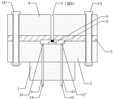
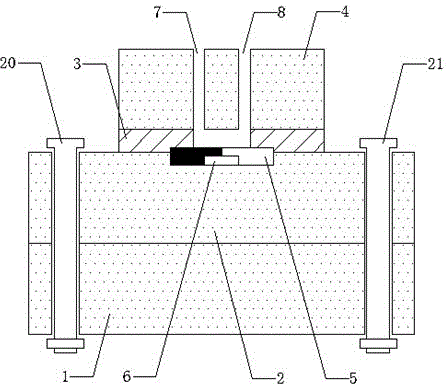
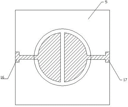
[0043] like figure 1 and figure 2 As shown, it includes a base 1, an intermediate layer 2, a silica gel gasket 3, a cover 4 and a quartz wafer 5; wherein, the base 1 is provided with a left probe through hole 9 and a right probe port 10, and the upper and lower ends are provided with the first A base through hole and a second base through hole; the center of the middle layer 2 is provided with a middle layer groove 6, and the bottom of the middle layer groove 6 is provided with a left probe through hole 9 and a right probe t...


PUM

PropertyMeasurementUnit
Thicknessaaaaaaaaaa
Thicknessaaaaaaaaaa

Abstract

The invention discloses a detection device for a quartz crystal microbalance. The detection device comprises a middle layer, a sealing gasket, a sealing cover and a quartz crystal wafer, wherein a middle layer groove is formed in the center of the middle layer; a left probe through hole and a right probe through hole are formed in the bottom end of the middle layer groove; a sample inlet and a sample outlet are formed in the sealing cover; the quartz crystal wafer is positioned in the middle layer groove; a quartz crystal wafer groove with a downward opening is formed in the center of the bottom end of the quartz crystal wafer; a left electrode and a right electrode are respectively arranged at the bottom end of the quartz crystal wafer groove; the sealing gasket is arranged between the sealing cover and the middle layer; a left spring pin probe penetrates through the left probe through hole to lead out the left electrode; a right spring pin probe penetrates through the right probe through hole to lead out the right electrode. By virtue of a flow cell structure, the detection device for the quartz crystal microbalance has the advantages of convenience in assembly and disassembly, reusability, simple structure, stable performance and the like, the quartz crystal microbalance can be miniaturized under high frequency, the quality-frequency sensitivity is improved, small molecules or trace substances can be detected, and the minimum sample amount of an object needing to be detected is small.

Description

technical field [0001] The invention relates to the technical field of sensing and detection, in particular to a quartz crystal microbalance detection device. Background technique [0002] Quartz Crystal Microbalance (QCM) is a sensor that detects trace substances based on the change of the resonant frequency caused by the change of the attachment mass on the wafer surface. It has the advantages of high sensitivity, simple structure, low cost, and especially does not require sample marking. , has been widely used as a detection and analysis tool in the fields of biology and chemistry. Quartz crystal microbalance is composed of an AT-cut quartz wafer and metal excitation electrodes fixed on both sides of the wafer. The excitation electrodes are generally derived from two socket pins welded on both sides of the chip respectively, and connected to the test instrument or the resonant circuit. [0003] The combination of quartz crystal microbalance and flow injection analysis t...

Claims


Application Information

Patent Timeline
IPC IPC(8): G01N5/02
Inventor 梁金星黄佳孔婷
Owner SOUTHEAST UNIV
Why Eureka
Try Eureka