Method for optical cable splicing with communication service uninterrupted and fiber coiling box

A technology for communication services and fiber reels, which is applied in the field of communication maintenance, can solve problems such as long welding time and affect the safe operation of power lines, and achieve the effect of enhancing corporate image, improving work ability, management level, and improving level.

Active Publication Date: 2014-02-05
STATE GRID CORP OF CHINA +2
View PDF5 Cites 1 Cited by
  • Summary
  • Abstract
  • Description
  • Claims
  • Application Information

AI Technical Summary

Problems solved by technology

[0004] The purpose of the present invention is to solve the problem that the communication service needs to be interrupted during the fusion splicing of the existing optical fiber interruption, and the fusion time is long, which seriously affects the safe operation of the power line, and to invent a method for performing optical cable fusion without interrupting the communication service. At the same time provide a matching fiber box

Method used


Image

  • Method for optical cable splicing with communication service uninterrupted and fiber coiling box

Examples


Embodiment 1

[0022] Such as figure 1 shown.

[0023] A method for splicing optical cables without interrupting communication services, comprising the following steps:

[0024] First, use the existing mature optical fiber fault location method to determine the location of the optical fiber fault;

[0025] Secondly, by releasing the coiled wire on the auxiliary pole at the fault location for at least one meter so that the sheath of the optical fiber at the fault location can be stripped at least 1-2 meters in length, the loose sleeve where the faulty optical fiber is located is determined according to the color or number Tube;

[0026] Thirdly, the loose tube that has not failed is placed in the fixed groove that matches the outer diameter of the loose tube added in the fiber box and positioned;

[0027] Fourth, use a slotting machine to peel off the loose tube where the faulty optical fiber is located. The length of the peeled off should be greater than the length of at least one coil in...

Embodiment 2

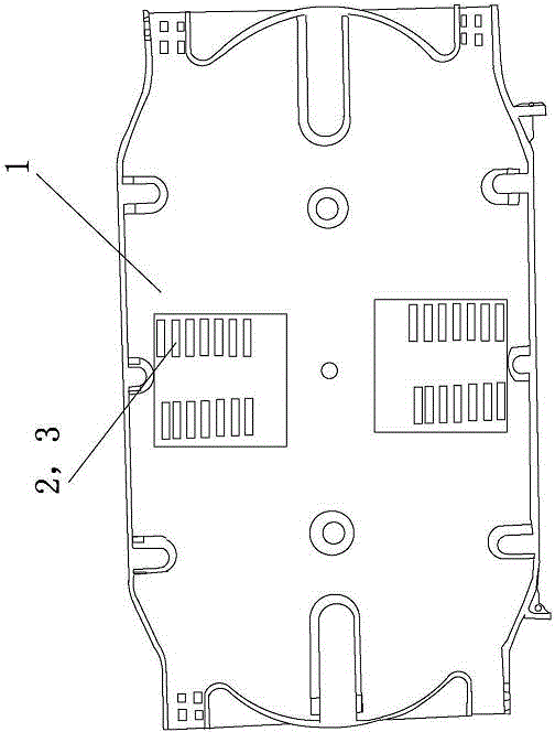
[0031] Such as figure 1 shown.

[0032] A disk fiber box for uninterrupted optical cable fusion splicing, which is characterized in that it includes a box body 1, and is characterized in that the box body 1 is provided with a fixing groove patch 2 for fixing a loose tube and a fiber core for fixing The fiber core coiling slot patch 3, the fixed slot patch 2 and the fiber core coiling slot patch 3 are pasted in different boxes 1 or stacked in the same box body 1.


PUM


Abstract

A method for optical cable splicing with communication service uninterrupted is characterized by comprising the following steps that firstly, the position of an optical fiber fault is determined according to a dedicated optical fiber fault position determination method; secondly, the outer sheath of an optical fiber at the fault position is stripped for at least 1-2m, and a loose tube where the optical fiber breaking down is located is determined; thirdly, a loose tube without faults is coiled in a fixed groove, with the outer diameter matched with that of the loose tube, of a loose tube coiling device and is located; fourthly, the loose tube where the optical fiber breaking down is stripped through a loose tube horizontal and transverse stripping cutter, and the length of the stripped part should be larger than the length of at least one circle of the loose tube coiled in a fiber coiling box; fifthly, a fiber core not breaking down in the stripped loose tube is coiled in a fiber core coiling groove in the fiber coiling box; finally, the optical fiber breaking down is spliced again through a welding machine and then is clamped to the fiber coiling box, and the fiber coiling box is arranged in a connector box to be fixed. The method achieves convenient splicing, and the communication service cannot be interrupted.

Description

technical field [0001] The invention relates to a communication maintenance technology, especially a technology for uninterrupted optical cable welding used in electric power communication, specifically a method for uninterrupted communication optical cable welding and a matching fiber box. Background technique [0002] At present, with the advancement of smart grid construction, the importance of power communication has become increasingly prominent. As the main physical platform for information transmission, optical cables are important for transmission such as relay protection, information collection and control of electrical equipment, two-way interactive information for users, and real-time information for electric meters. information. As the technical support for the safe, stable and high-quality operation of the power grid, the communication optical network is playing an increasingly important role. Therefore, the construction of communication optical cables and the r...

Claims


Application Information

Patent Timeline
Patent Type & Authority Applications(China)
IPC IPC(8): G02B6/255G02B6/44
Inventor 韦磊王宏延蒋陵顾松葛嵩于阳张雳
Owner STATE GRID CORP OF CHINA
Why Eureka
Try Eureka