Carbon fiber smashing equipment

A crushing equipment and carbon fiber technology, applied in grain processing, etc., can solve the problems of high price, affecting production efficiency, production troubles, etc., and achieve the effect of adjustable crushing fineness, excellent performance and high efficiency, and small footprint

Inactive Publication Date: 2014-02-12
HENAN JIXING MACHINERY
View PDF12 Cites 14 Cited by
  • Summary
  • Abstract
  • Description
  • Claims
  • Application Information

AI Technical Summary

Problems solved by technology

For example, when crushing carbon fiber materials, a sieve-type pulverizer was used. Since the bottom of the screen is used to adjust the crushing fineness of the material, it is difficult to process the too dense screen, so the maximum crushing fineness of the material can only reach 60. In addition, the bottom of the screen is easily damaged and needs to be replaced in time, which will bring trouble to production and affect the production progress
A kind of Raymond mill was also used. Because the outer surface of the grinding roller is smooth, it is not easy to break the fiber material, and the bearing connecting the support arm and the grinding roller is in the crushing room for a long time, which is easy to cause damage to the bearing, and even breaks down after working for less than 24 hours. It is necessary to stop the machine to replace the bearing, which directly affects the improvement of production efficiency and output
This phenomenon is more serious if it is used to capture the gas with high dust concentration. Therefore, the application of jet pulse cleaning bag dust removal is limited to a certain extent.
At the same time, the above-mentioned equipment is used for stand-alone production instead of a production line, and the price is expensive, it is difficult to popularize and apply, it cannot form a production scale, and it is difficult to guarantee product quality

Method used


Image

  • Carbon fiber smashing equipment
  • Carbon fiber smashing equipment
  • Carbon fiber smashing equipment

Examples


Embodiment Construction

[0023] Specific embodiments of the present invention will be described in detail below in conjunction with the accompanying drawings.

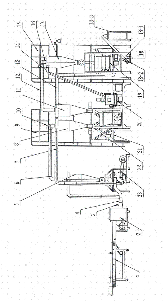
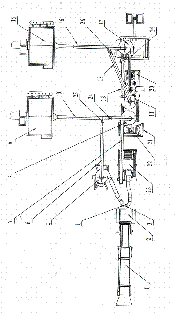
[0024] figure 1 , figure 2 Among them, the incoming material conveyor 1 and the cutting machine 2 are detachably plugged. Cutting machine 2 passes belt 1 # The first air delivery pipeline 4 of the pneumatic valve 3 communicates with the coarse pulverizer 23 and the first cyclone separator 5 respectively. The first cyclone separator 5 is provided with 2 # The first separation air delivery pipeline 6 of the pneumatic valve 25 and the belt 3 #The second separation air delivery pipeline 10 of the pneumatic valve 24 is communicated, and the second separation air delivery pipeline 10 is communicated with the second cyclone type separator 8 and communicated with the first air box type pulse dust collector 9, and the second cyclone separator 8 is also communicated with the coarse pulverizer 23 through the second air delivery pipeline 7, and comm...


PUM


Abstract

The invention discloses carbon fiber smashing equipment. The carbon fiber smashing equipment is mainly composed of a supplied material conveyor, a cut-off machine, a coarse pulverizer, an atomizer mill, a screening machine and a finished product conveyor as well as a cyclone separator and a pulse dust collector which are connected through a corresponding air conveying pipeline. The equipment can produce carbon fiber products with multiple lengths and finenesses, the highest fineness can achieve 300 meshes, the annual output can achieve 1000 tons, and the requirements of carbon fiber sections and thin powders of different specifications required by a carbon fiber production processing industry are fully achieved. The carbon fiber smashing equipment disclosed by the invention has the characteristics that the property is good, the efficiency is high, the structure is compact, the floor space is small, the yield is high, the operation is convenient, the smashing fineness is adjusted, the carbon fiber smashing equipment is wear-resisting and is easy to maintain, the labor is saved, the electricity is saved, and the environment can achieve the standard; the carbon fiber smashing equipment is ideal carbon fiber smashing equipment instead of imported equipment.

Description

technical field [0001] The invention relates to a crushing device, in particular to a carbon fiber crushing device. It is suitable for the crushing of carbon fiber materials and is an indispensable equipment for the last grinding process in the carbon fiber production process. Background technique [0002] Carbon fiber is a high-tech product, and it is a multi-functional and multi-purpose functional material and structural material. And carbon fiber is a kind of material that is very difficult to crush and process. Carbon fiber itself looks soft, but is actually very hard. It is very difficult to obtain carbon fiber with a certain fineness. However, carbon fiber needs to be pulverized before it can be combined with resin, metal, ceramic, rubber and other matrices to form composite materials with excellent performance. It has been applied in many fields. [0003] At present, the equipment used in grinding and deep processing to produce carbon fiber is all imported equipmen...

Claims


Application Information

Patent Timeline
Patent Type & Authority Applications(China)
IPC IPC(8): B02C21/00B02C23/02
Inventor 安绍录金学海安纪来安伟举安伟康
Owner HENAN JIXING MACHINERY
Why Eureka
Try Eureka