Rotating compressor and refrigeration cycle device
A technology of rotary compressor and compression mechanism, which is applied in the direction of rotary piston machinery, rotary piston pump, rotary piston type/oscillating piston type pump components, etc., which can solve the problem of high compatibility between lubricating oil and refrigerant and low oil viscosity and other issues to achieve the effect of ensuring reliability and preventing the reduction of compressor efficiency
- Summary
- Abstract
- Description
- Claims
- Application Information
AI Technical Summary
Problems solved by technology
Method used
Image
Examples
Embodiment 1
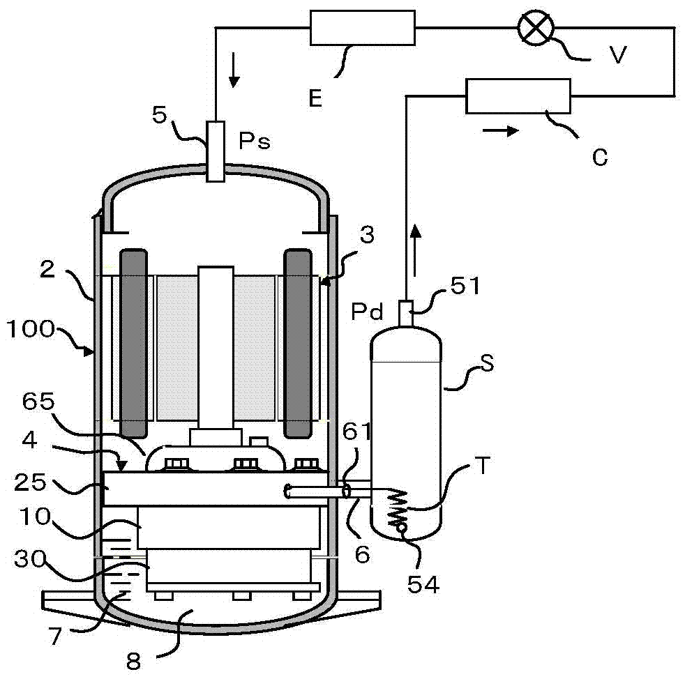
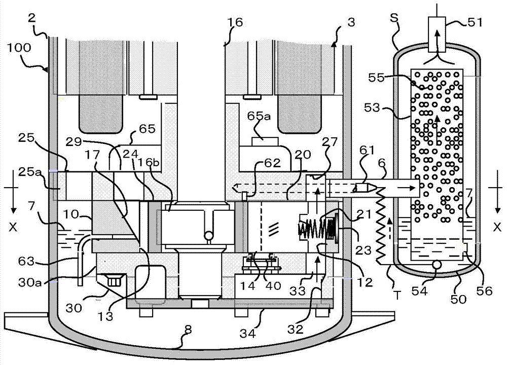
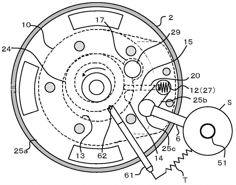
[0042] The rotary compressor 100 and the refrigeration cycle of Embodiment 1 of the present invention are as figure 1 shown. The rotary compressor 100 is composed of a compression mechanism 4 installed in the inner diameter of the hermetic casing 2, and an electric motor 3 arranged above it. The compression mechanism 4 is made up of the main bearing 25 and the auxiliary bearing 30 fixed in the inner diameter of the cylinder 10 and the housing 2, and they are assembled by screws. The exhaust pipe 6 and the oil injection pipe 61 connected to the outer periphery of the main bearing 25 are connected to the oil separator S. A capillary T is arranged between the oil injection pipe 61 and the oil separator S in order to adjust the amount of oil supplied to the compression chamber. In addition, an air intake pipe 5 is arranged at the upper end of the casing 2, and oil 7 is sealed in an oil pool 8. In addition, the suction pipe 5 may be arranged between the motor 3 and the compressi...
Embodiment 2
[0063] Figure 4 The shown embodiment 2 is a design in which exhaust mufflers are arranged on both sides of the auxiliary bearing 30 and the main bearing 25 . Therefore, the main bearing 25 also requires the exhaust muffler (A) 26 in addition to the exhaust muffler (B) 32 of the sub bearing 30 . Exhaust pipe 6 is just passable in the exhaust muffler of a certain side, but Figure 4 Configured in the exhaust muffler (B) 32, Figure 5 Then, the exhaust pipe 6 is arranged in the exhaust muffler (A) 26 .
[0064] In the main bearing 25 , the mixed refrigerant discharged from the exhaust hole 14 opening to the compression chamber 13 to the exhaust muffler (A) 26 passes through the vane cavity 12 and joins the high-pressure refrigerant of the exhaust muffler (B) 32 from the exhaust pipe 6 Flow out to the oil separator S. Thereafter, the oil was separated and the refrigerant was discharged into the refrigeration cycle in the same manner as in Example 1. In addition, the oil sepa...
Embodiment 3
[0066] Figure 6 Example 3 shown shows that the vane lubrication method and the oil control method of Example 1 can be applied to a 2-cylinder low-pressure rotary compressor.
[0067] The compression mechanism 4 of the 2-cylinder rotary compressor 200 consists of a cylinder (A) 10a and a cylinder (B) 10b each having a compression chamber 13a and a compression chamber 13b, a partition plate 36 disposed therebetween, and a piston 24a provided in each cylinder. Consists of piston 24b, slide plate 20a and slide plate 20b, eccentric shaft 16 for revolving the two pistons, main bearing 25 and sub-bearing 30 for slidingly supporting the eccentric shaft 16 and connecting the two cylinders respectively .
[0068] The main bearing 25 and the sub-bearing 30 are provided with exhaust holes 14 respectively opening in the compression chamber 13a and the compression chamber 13b, and the main bearing 25 and the sub-bearing 30 are respectively equipped with an exhaust muffler and an exhaust m...
PUM
 Abstract
Description
Claims
Application Information
 - R&D
- Intellectual Property
- Life Sciences
- Materials
- Tech Scout
- Unparalleled Data Quality
- Higher Quality Content
- 60% Fewer Hallucinations
Browse by: Latest US Patents, China's latest patents, Technical Efficacy Thesaurus, Application Domain, Technology Topic, Popular Technical Reports.
© 2025 PatSnap. All rights reserved.Legal|Privacy policy|Modern Slavery Act Transparency Statement|Sitemap|About US| Contact US: help@patsnap.com


