
Solenoid valve

A solenoid valve and magnetic core technology, applied in the field of solenoid valves, can solve problems such as difficult manufacturing and complex structure, and achieve the effects of reducing manufacturing costs, improving work reliability, and excellent responsiveness

Active Publication Date: 2014-02-12
UNICK
View PDF7 Cites 0 Cited by
  • Summary
  • Abstract
  • Description
  • Claims
  • Application Information

AI Technical Summary

Problems solved by technology

However, the solenoid valve of the ball valve type or the poppet valve type needs to provide an orifice separately at the inflow port for supplying the working oil, so it has the disadvantages that the structure is complicated and it is not easy to manufacture.

Method used


Image

  • Solenoid valve
  • Solenoid valve
  • Solenoid valve

Examples


Embodiment Construction

[0031] Embodiments of the present invention will be described in detail with reference to the accompanying drawings. Hereinafter, in describing the embodiments of the present invention, and in attaching reference numerals to components, the same components are denoted by the same reference numerals as much as possible even if they are shown in different drawings.

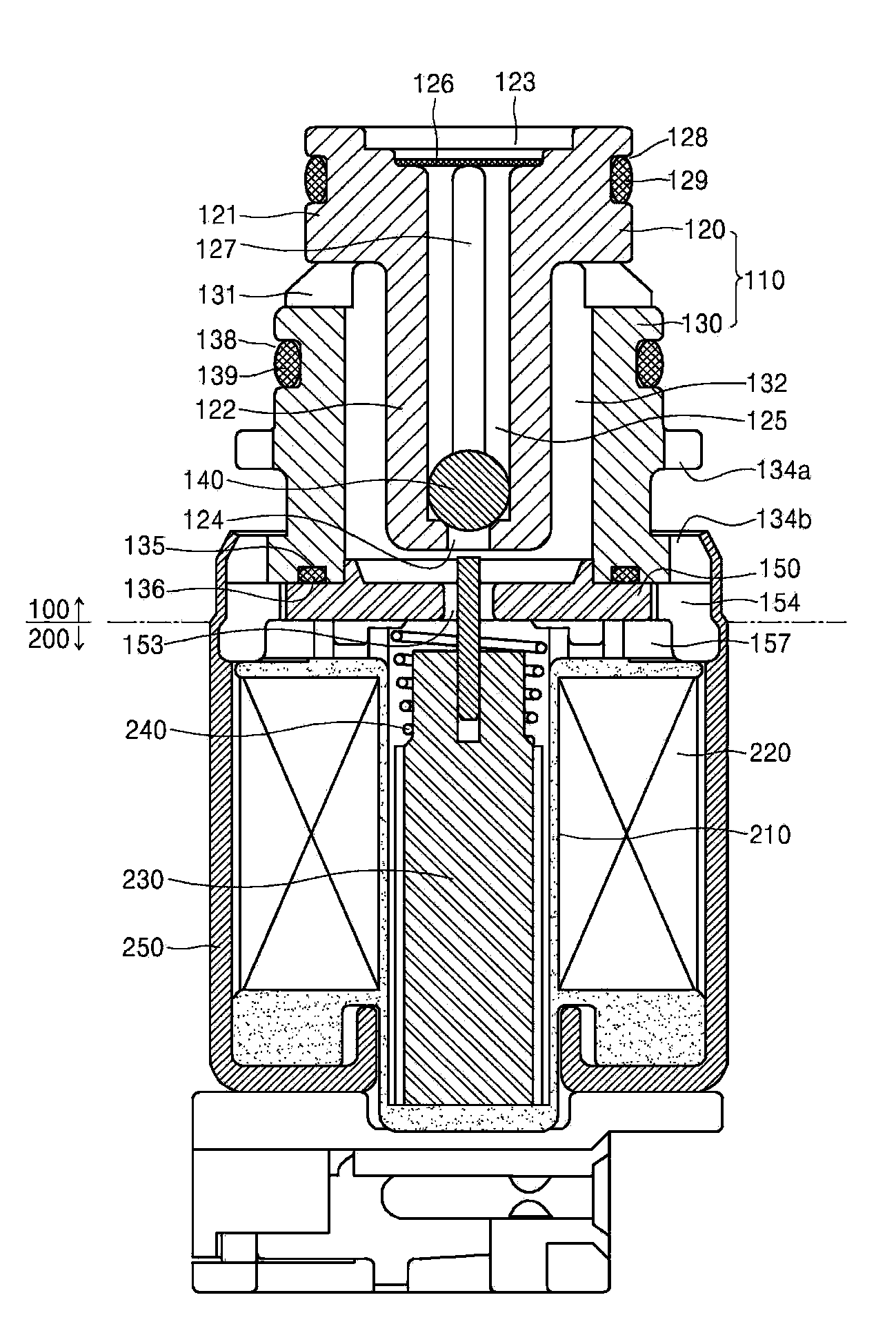
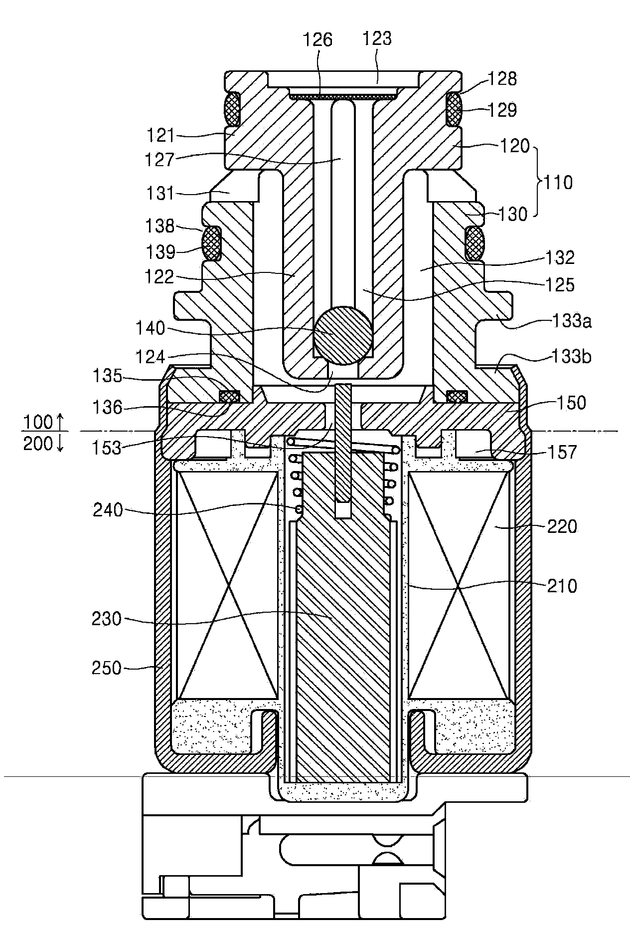
[0032] A solenoid valve according to an embodiment of the present invention includes a valve 100 for controlling the flow of fluid and a solenoid 200 for operating the valve 100 .

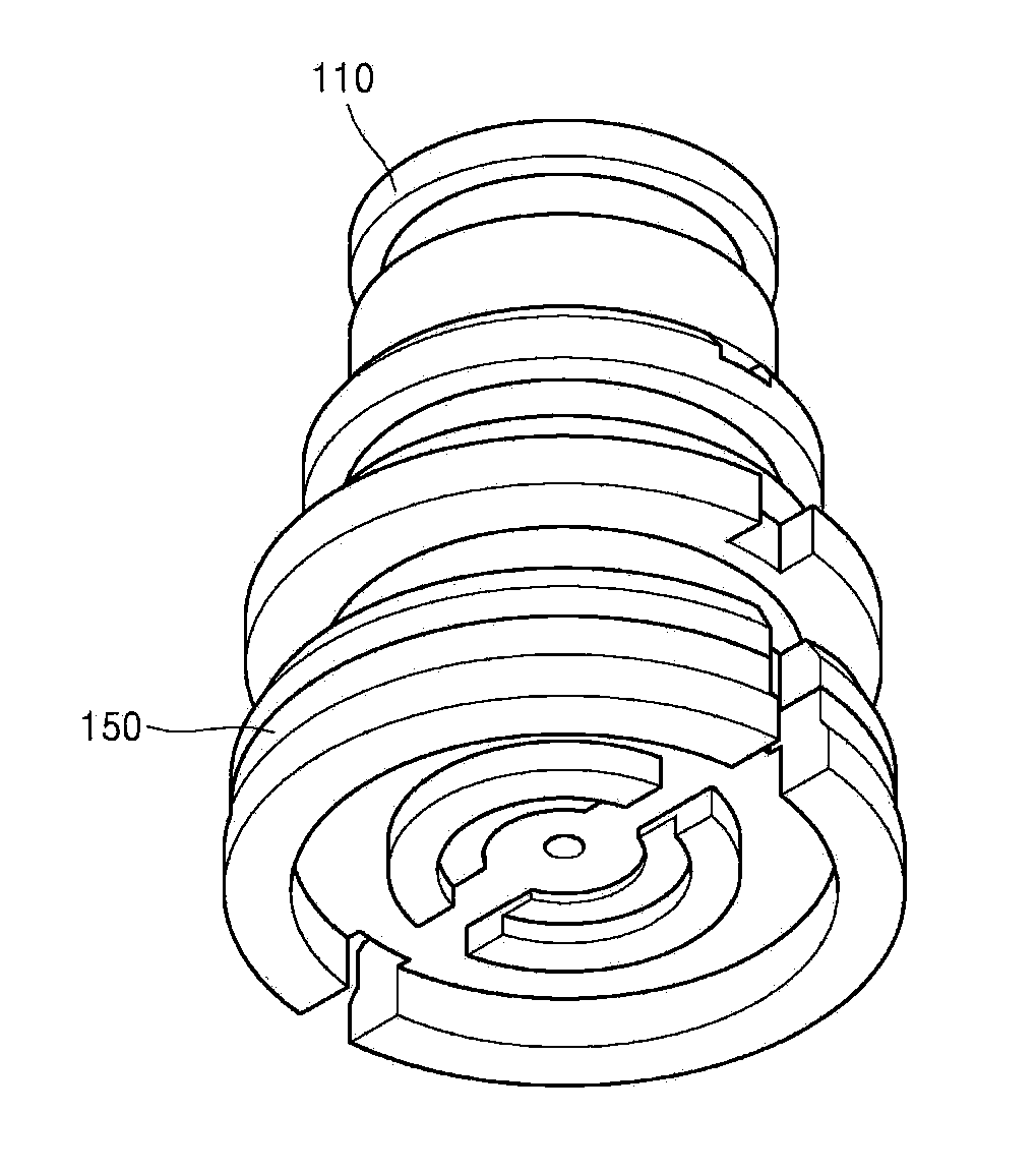
[0033] like figure 1 and figure 2 As shown, the valve 100 includes: a bracket 110 ; a ball 140 arranged inside the bracket 110 ; a magnetic core 150 combined with the lower end of the bracket 110 ;

[0034] The stent 110 is a double tube structure composed of an inner tube 120 and an outer tube 130 . The outer tube 130 surrounds the middle and lower ends of the inner tube 120 , and the lower end of the outer tube 130 is longer than t...


PUM


Abstract

The invention relates to a solenoid valve served as a pressure control valve unit mounted in the hydraulic control unit of an automatic transmission. The solenoid valve comprises a valve configured to control a flow of a fluid; and a solenoid configured to operate the valve. The valve includes: a holder having a double tube structure of an inner tube and an outer tube; a first connection port formed at one end of the inner tube to connect a supply passage with a control passage; a ball installed within the supply passage to open and close the first connection port; a magnetic core coupled to one end of the outer tube; a second connection port formed in the magnetic core and connected to the control passage; and a rod configured to pass through the second connection port to be moved by the solenoid. Due to the adoption of the above structure, a coupling ring is adhered to the inner wall of the outer tube when the holder and the magnetic core are coupled to each other. Therefore, the coaxial deviation of the holder and the magnetic core is avoided. The assembility and the operability are improved, and the cost is lowered. Meanwhile, the number of elements is minimized and the operation reliability is improved.

Description

technical field [0001] The present invention relates to a solenoid valve, and more particularly, to a solenoid valve used as a valve mechanism for adjusting the hydraulic pressure of an automatic transmission. Background technique [0002] The transmission is a device that converts the power generated by the engine into an appropriate rotational force and transmits it according to the speed and load of the vehicle. Transmissions are classified into manual transmissions and automatic transmissions according to the transmission method, and most of the automobiles produced today are equipped with automatic transmissions. [0003] An automatic transmission is a transmission that automatically performs a shifting process in a predetermined mode. Such an automatic transmission includes a torque converter, a working mechanism, a star gear device, a hydraulic control mechanism, and an electromagnetic control device. Furthermore, in the above-described configuration, the hydraulic ...

Claims


Application Information

Patent Timeline
Patent Type & Authority Applications(China)
IPC IPC(8): F16K31/06F16K27/12F16K37/00
CPCF16K31/06H01F7/1607F16K27/029F16K31/0665Y10T137/87217H01F7/16
Inventor 李昌勳鲁義东李基龙
Owner UNICK
Learn More