Air cooling dry type slag conveying system of coal-fired boiler

A coal-fired boiler, air-cooled technology, applied in the direction of lighting and heating equipment, can solve the problems of large damper diameter, affecting equipment operation, accumulation jams, etc., to reduce the wear and tear of conveying and crushing equipment, improve boiler thermal efficiency, and improve Accurate effect of air volume control

Active Publication Date: 2014-02-12
QINGDAO DANENG ENVIRONMENTAL PROTECTION INC
View PDF4 Cites 5 Cited by
  • Summary
  • Abstract
  • Description
  • Claims
  • Application Information

AI Technical Summary

Problems solved by technology

[0003] In the traditional air-cooled dry slag conveying system, the cooling air mainly exchanges heat with the upper surface of the ash on the conveyor belt, and the cooling performance is poor. It is only suitable for the working conditions with a small amount of bottom slag and thin cinder thickness
Due to poor cooling performance, more cooling air is needed, the temperature of the air entering the furnace is low, and the air volume is large, which causes the center of the boiler flame to move upward, the temperature of the exhaust gas is high, and the thermal efficiency of the boiler is low
And because the air door has a large diameter, large air volume and fast wind speed, and it is installed on the top of the dry slag machine head, which is the slag conveying area, which has a great impact on the conveyance of fine ash and small slag on the conveyor belt, and part of it is blown back to the lower end of the conveyor belt , part of it is blown up and falls to the bottom of the equipment casing, causing accumulation or even jamming, affecting the operation of the equipment, and the transmission efficiency is low

Method used


Image

  • Air cooling dry type slag conveying system of coal-fired boiler
  • Air cooling dry type slag conveying system of coal-fired boiler
  • Air cooling dry type slag conveying system of coal-fired boiler

Examples


Embodiment Construction

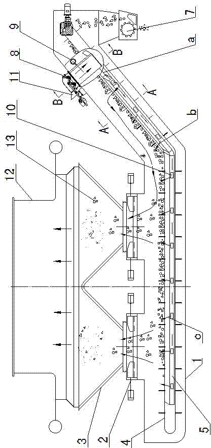
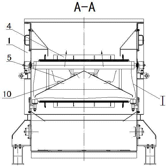
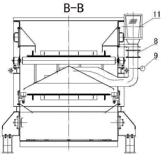
[0027] exist Figure 1 to Figure 6 Among them, the coal-fired boiler air-cooled dry slag conveying system of the present invention includes a casing 1, a large slag extrusion device 2 installed above the tail of the casing, and a slag hopper 3 installed on the casing above the large slag extrusion device , the ash and slag material conveyor belt 4 installed on the casing is located below the large slag extrusion device, and the female air duct 5 installed on the casing between the process and the return ash and slag material conveyor belt and provided with several small air outlets 10 is installed. Ash baffle 6 on the small tuyere of the main air duct, slag breaker 7 installed under the head of the casing, automatic flow regulating valve 8 installed in the air inlet 11 of the casing head, installed under the automatic flow regulating valve Flow meter 9 on the tuyere.

[0028] In the air-cooled dry slag conveying system of the coal-fired boiler of the present invention, the sa...


PUM


Abstract

An air cooling dry type slag conveying system of a coal-fired boiler comprises a machine shell, a large slag extrusion device installed above the tail portion of the machine shell, a slag bucket located above the large slag extrusion device and installed on the machine shell, an ash slag material conveying belt located below the large slag extrusion device and installed on the machine shell, a primary air pipe which is located between an entry strip ash slag material conveying belt and a return strip ash slag material conveying belt, installed on the machine shell and provided with a plurality of small air ports, an ash stopping plate installed on the small air ports of the primary air pipe, a slag smashing machine installed below the head of the machine shell, an automatic flow regulating valve installed in an air inlet in the head of the machine shell, and a flow meter installed on an air port below the automatic flow regulating valve. The air cooling dry type slag conveying system of the coal-fired boiler is good in cooling effect, rapidly raises air temperature, controls air volume accurately, enables the heat efficiency of the boiler to be high, saves energy, protects the environment, is high in conveying efficiency, is long in service life, and can be widely applied to the slag conveying process of the coal-fired boiler.

Description

technical field [0001] The invention relates to an air-cooled dry slag conveying system for a coal-fired boiler, which can be widely used in the slag conveying process of the coal-fired boiler. Background technique [0002] In recent years, with the rapid development of the economy, the per capita energy consumption has also increased rapidly with the continuous improvement of people's living standards, thus making environmental problems more and more prominent. Therefore, energy saving, consumption reduction, development and application of new technologies of water saving, energy saving and environmental protection are the current development trend of the world. In the thermal power generation industry, the use of dry slag conveying technology to replace the traditional hydraulic slag conveying technology is the current development direction of slag removal in the entire power industry. [0003] In the traditional air-cooled dry slag conveying system, the cooling air mainl...

Claims


Application Information

Patent Timeline
Patent Type & Authority Applications(China)
IPC IPC(8): F23J1/02
Inventor 张光荣姜衍更
Owner QINGDAO DANENG ENVIRONMENTAL PROTECTION INC
Why Eureka
Try Eureka