Random position point optical fiber distributed sonic sensor

A fiber optic distributed, acoustic wave sensor technology, applied in the direction of measuring ultrasonic/sonic/infrasonic waves, instruments, measuring devices, etc., can solve the problems of complex time division multiplexing technology, measurement range limitation, system cost increase, etc., to reduce technical difficulty, Effect of reducing the required quantity and reducing the system cost

Active Publication Date: 2014-02-12
LASER RES INST OF SHANDONG ACAD OF SCI
View PDF5 Cites 17 Cited by
  • Summary
  • Abstract
  • Description
  • Claims
  • Application Information

AI Technical Summary

Problems solved by technology

However, the traditional acoustic wave measurement methods have problems such as large device volume and limited measurement range by the amplifier device, and the traditional acoustic wave measurement method can only perform point measurement, which is limited in practical application. Therefore, the development of a high-performance acoustic wave measurement system is potential. must do
[0003] In the prior art, the research on the acoustic wave sensing system based on optical fiber technology has been very extensive. For the acoustic wave phase, the point acoustic wave sensor of the fiber grating probe or the electric probe is mostly used. This kind of sensing system can only measure the acoustic wave phase information near the probe; Optical fiber distributed sensors based on optical time domain reflection technology are mostly used for the position of sound waves. This kind of sensing system can only determine the position of the sound source on the sensing fiber, but it is difficult to know the information of the sound source itself.
In summary, the existing measurement methods generally have the problem that it is difficult to balance the acoustic wave phase measurement and the acoustic wave position measurement
If it is necessary to monitor the acoustic phase and position of a sound source at a random position at the same time, two systems must be arranged in the measurement space, one for the acoustic phase measurement and the other for the acoustic position measurement, not only need to lay a position sensing optical fiber , it is also necessary to match a large number of acoustic wave phase sensors in the measurement range to cover the entire measurement range. For the demodulation of the acoustic wave phase in the back-reflected light, the system generally needs to use complex time-division multiplexing technology, resulting in a substantial increase in system cost
In the prior art, when the above-mentioned two measurement methods are used, the two measurement devices need to be set up separately, that is, in order to cooperate with the measurement of the position of the sound wave, not only a position sensing optical fiber needs to be laid, but also a large number of sound waves need to be matched within the measurement range. The phase information of the sound wave can only be obtained by using a phase sensor to cover the entire measurement range; for the demodulation of the sound wave phase in the back-reflected light, the system generally needs to use complex time-division multiplexing technology; in addition, the corresponding light source supply device, filter device , mixing device and other equipment also need to be set separately for the two measuring devices

Method used


Image

  • Random position point optical fiber distributed sonic sensor
  • Random position point optical fiber distributed sonic sensor
  • Random position point optical fiber distributed sonic sensor

Examples


Embodiment 1

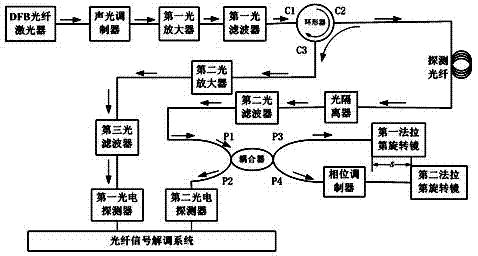
[0031] Example 1 uses a narrow-linewidth, low-noise DFB fiber laser (RFLM-25-3-1550-1, NP Photonics, wavelength 1550nm) as a light source, and then passes through an acousto-optic modulator (ZY-AOM-SM-1550-10 , Beijing Zhongke Ziyu Photoelectric Technology Co., Ltd.) to form a forward incident pulse, and then pass through the first optical amplifier (PB-pluse-EDFA-M-CB-0-0-FC / APC, Beijing Better Optical Technology Co., Ltd. ) and incident to the circulator C1 end after the first optical filter. The C2 end of the circulator is connected to the detection fiber. The detection fiber is an ordinary fiber, assuming that the length of the sensing fiber is 2 km and the pulse width τ of the laser pulse is 50 ns, then the spatial resolution ΔL is 5 m as mentioned above. The Rayleigh backscattering signal of the detection fiber passes through the C3 end of the circulator, passes through the second optical amplifier and the third optical filter, and then directly enters the first photode...


PUM


Abstract

The invention provides a random position point optical fiber distributed sonic sensor which comprises a DFB fiber laser, an acoustic optical modulator, a first optical amplifier, a circulator and a detection optical fiber. An optical signal returned by the detection optical fiber is output through the end C3 of the circulator and sent to a third optical filter through a second optical amplifier; the third optical filter outputs the optical signal to a first photoelectric detector; a forward incident pulse optical signal which passes through the detection optical fiber and continues to be transmitted enters a second optical filter through an optoisolator; the second optical filter outputs the optical signal to a coupler and is connected with a first Faraday rotation mirror; the coupler is connected with a second Faraday rotation mirror through a phase modulator; the coupler outputs the optical signal to a second photoelectric detector; the first photoelectric detector and the second photoelectric detector output electric signals to an optical fiber signal demodulation system. By the adoption of the scheme that a sonic wave position measuring device based on back phase Rayleigh scattering and a sonic wave phase measuring device based on Michelson interference are combined with each other through the same detection optical fiber, a time division multiplexing technology is not needed.

Description

technical field [0001] The invention relates to an optical fiber sensor, in particular to an optical fiber distributed acoustic wave sensor with random position points. Background technique [0002] Acoustic measurement technology is widely used in the exploration and development of offshore oil and gas resources, as well as in downhole microseismic, sound velocity, flow, etc. However, the traditional acoustic wave measurement methods have problems such as large device volume and limited measurement range by the amplifier device, and the traditional acoustic wave measurement method can only perform point measurement, which is limited in practical application. Therefore, the development of a high-performance acoustic wave measurement system is potential. It must be done. [0003] In the prior art, the research on the acoustic wave sensing system based on optical fiber technology has been very extensive. For the acoustic wave phase, the point acoustic wave sensor of the fibe...

Claims


Application Information

Patent Timeline
Patent Type & Authority Applications(China)
IPC IPC(8): G01H9/00G01S17/06
Inventor 王晨刘小会尚盈王昌彭纲定郭士生
Owner LASER RES INST OF SHANDONG ACAD OF SCI
Why Eureka
Try Eureka