
Imaging method of synthetic aperture radar in large squint angle mode

A technology of synthetic aperture radar and imaging method, which is applied in the directions of radio wave reflection/re-radiation, utilization of re-radiation, and measurement devices, which can solve problems such as ignoring signal change characteristics, and achieve avoidance of interpolation operations, high computing efficiency, and precise focusing Effect

Inactive Publication Date: 2014-02-12
INST OF ELECTRONICS CHINESE ACAD OF SCI
View PDF8 Cites 13 Cited by
  • Summary
  • Abstract
  • Description
  • Claims
  • Application Information

AI Technical Summary

Problems solved by technology

The traditional Chirp-Z transform can realize the SAR echo signal focusing without interpolation operation, but it can only be applied to the direct In side view or small squint mode

Method used

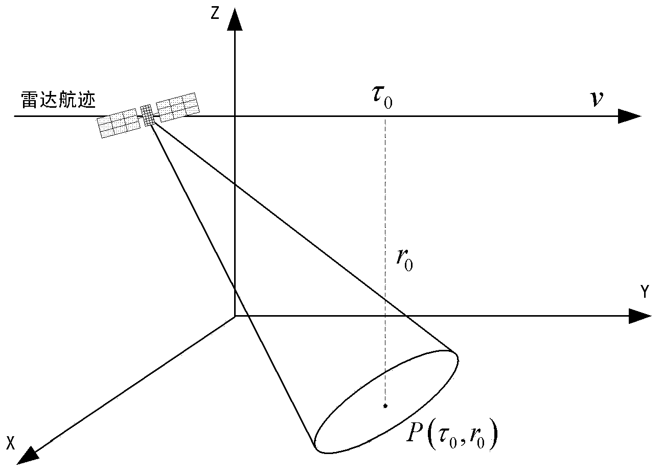

Image

  • Imaging method of synthetic aperture radar in large squint angle mode
  • Imaging method of synthetic aperture radar in large squint angle mode
  • Imaging method of synthetic aperture radar in large squint angle mode

Examples


Embodiment Construction

[0022] In order to make the object, technical solution and advantages of the present invention clearer, the present invention will be described in further detail below in conjunction with specific embodiments and with reference to the accompanying drawings.

[0023] The imaging method of the synthetic aperture radar in high squint mode of the present invention can be implemented in hardware or in software. For example, it can be installed and executed in the form of software on personal computers, industrial computers and servers, and the method of the present invention can also be embodied in the form of embedded chips in the form of hardware. Specific embodiments of the present invention will be described below with reference to the accompanying drawings.

[0024] According to the SAR echo signal time-domain model, spectrum model and time-frequency domain mapping relationship, by introducing a perturbation function in the azimuth Doppler domain-range time domain or Doppler-t...


PUM


Abstract

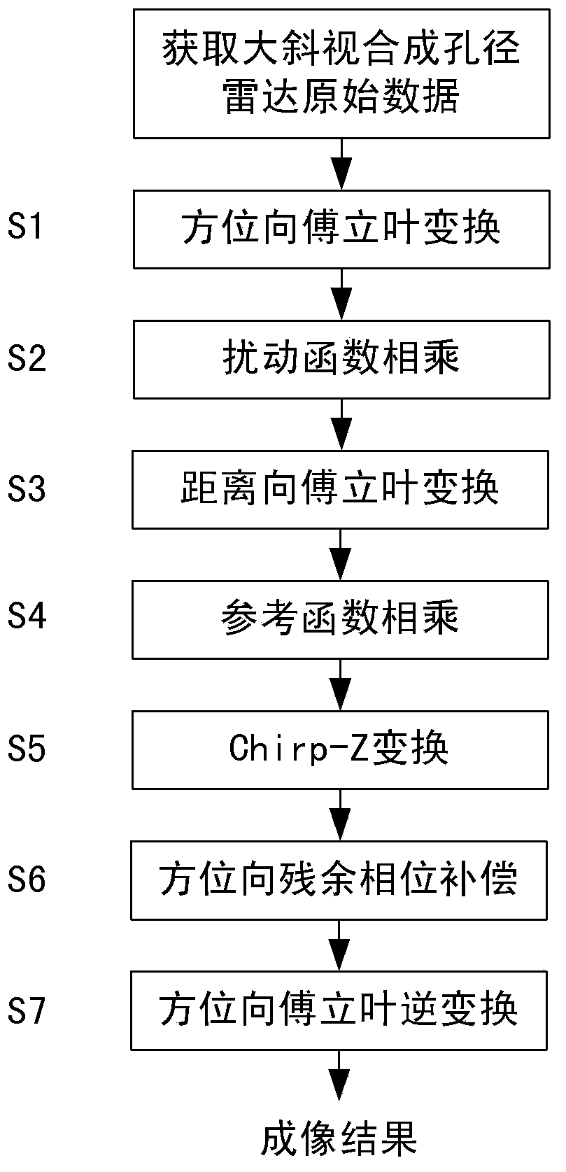
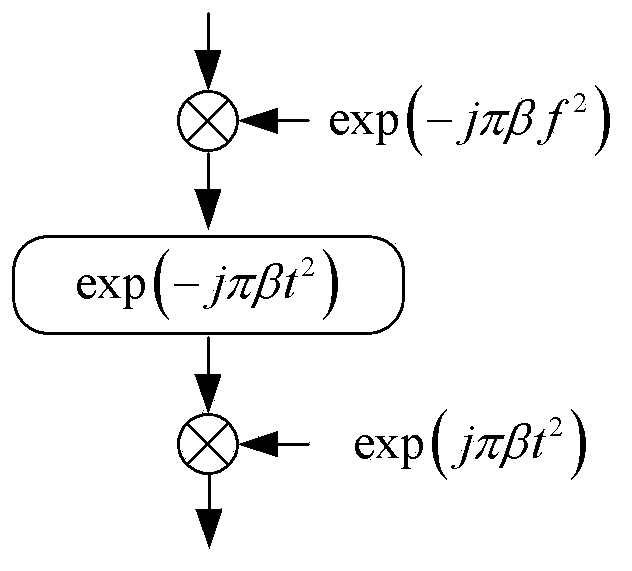
The present disclosure provides an imaging method for a Synthetic-Aperture Radar (SAR) in a high squint mode. The method includes: perform perturbation function multiplication for an echo signal in the azimuth Doppler domain-range time domain to eliminate the dependence of an echo signal quadratic azimuth-range coupling factor on the change of a target slant range; perform reference function multiplication in the two-dimensional frequency domain, wherein the reference function is a conjugate function of a point target echo spectrum at a reference slant range; complete compensation of all phases, which do not vary with the range, of a two-dimensional spectrum through the multiplication of the two-dimensional spectrum and the reference function; rectify the differential range migration factor of the echo signal in the two-dimensional frequency domain by utilizing Chirp-Z transform, complete range migration rectification by performing convolution once and phase multiplication twice; compensate an azimuth residual phase through the azimuth phase multiplication, and perform azimuth compression to obtain a focused SAR image. The method of the present disclosure can perform highly efficient and precise imaging for high squint SAR data.

Description

technical field [0001] The invention belongs to the technical field of microwave remote sensing observation of the earth, and relates to an accurate focusing method in a high squint mode based on Chirp-Z transformation, which is applied to the field of airborne and spaceborne synthetic aperture radar high oblique angle of view earth observation. Background technique [0002] Synthetic aperture radar technology is currently an important technical means for ground remote sensing, imaging and monitoring. It can realize all-day, all-weather high-resolution imaging of a large coverage area. Wide range of applications. Synthetic aperture radar image is a representation of electromagnetic scattering characteristics of scene echo data after signal processing. The traditional Chirp-Z transform imaging method corrects the dependence of the first-order range-azimuth coupling on the slant range of the target by scaling Fourier transform in the two-dimensional frequency domain. The tra...

Claims


Application Information

Patent Timeline
IPC IPC(8): G01S13/90
CPCG01S13/9011G01S13/9041
Inventor 邓云凯刘悦王宇
Owner INST OF ELECTRONICS CHINESE ACAD OF SCI
Learn More