
Method for automatically monitoring welding contraction deformation of steel structure

A shrinkage deformation and automatic monitoring technology, applied in welding equipment, welding equipment, auxiliary welding equipment, etc., can solve the problems of inability to display shrinkage deformation results in real time, low labor efficiency, delay in construction period, etc., and achieve real-time grasp of stability and quality, The effect of reducing labor intensity and high degree of automation

Inactive Publication Date: 2014-02-19
GUANGXI UNIV +1
View PDF8 Cites 7 Cited by
  • Summary
  • Abstract
  • Description
  • Claims
  • Application Information

AI Technical Summary

Problems solved by technology

[0004] As a common residual deformation in welding, steel structure welding shrinkage deformation has been continuously concerned and extensively studied. Traditional welding shrinkage deformation measurement mainly relies on manual measurement, such as steel ruler (vernier caliper) measurement, three-dimensional coordinate observation method, And it has to be measured when the weldment is cooled to room temperature. The labor efficiency is low and the construction period is delayed, and the precision is also low. The shrinkage and deformation results cannot be displayed in real time during the welding process, and it cannot be fully automated.
In recent years, digital camera numerical image processing method has appeared to measure shrinkage and deformation. The measurement accuracy of digital camera numerical image processing method is related to the pixels of the camera, but the requirements for equipment and software are high, the price is high, and it is not suitable for popularization. Therefore, in steel A high-precision, automatic, real-time dynamic monitoring method for welding shrinkage deformation is urgently needed in the field of structural welding processing

Method used


Image

  • Method for automatically monitoring welding contraction deformation of steel structure
  • Method for automatically monitoring welding contraction deformation of steel structure
  • Method for automatically monitoring welding contraction deformation of steel structure

Examples


Embodiment 1

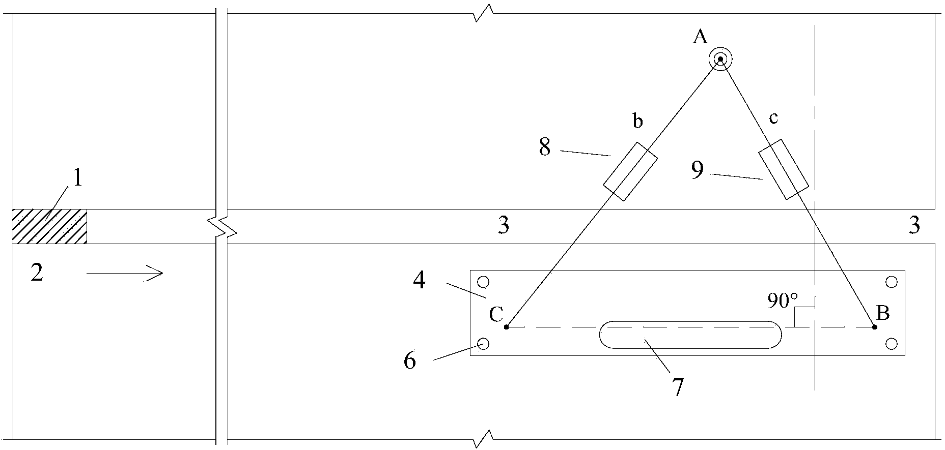
[0031] Such as figure 2 Shown, in the welding process of certain unequal thickness steel plate, apply the present invention as follows:

[0032] Among them, the monitoring equipment consists of two displacement sensors b and c (the end of the transmission rod and the support rod of the displacement sensor has a hinge, and the transmission rod has a length adjustment nut and a scale that can directly read the center distance between the two hinges), with a magnet The base A of the fixed sensors b and c, the control display panel and the chassis etc.; the embedded computer has the functions of data processing, storage and real-time display, and can also export the data for processing.

[0033] Install the monitoring equipment at the other end of the starting welding end. Place the chassis of the monitoring equipment parallel to the welding seam on one side of the welded steel plate or component, and place the base A on the other side of the welded steel plate or component. The...


PUM


Abstract

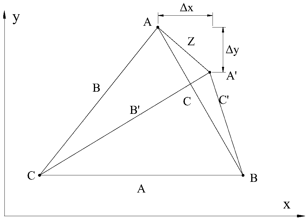
The invention discloses a method for automatically monitoring welding contraction deformation of a steel structure. An inventor conducts theoretical deviation through a displacement sensor to obtain contraction deformation computational formulas seen from formula (1) to formula (6) and sets up the automatic monitoring method according to the formulas. The method is simple in device, easy to operate, high in automation degree, free of manual interference and capable of lowering the labor intensity of people. Contraction deformation values in two perpendicular directions and a total contraction deformation value can be displayed in real time, and real-time grasping of stability and quality of the welding technology can be facilitated. The monitoring result is higher in accuracy compared with the monitoring result obtained through a conventional method, and the accuracy can reach 0.01mm. When the method is applied to the steel structure welding field, the contraction deformation can be accurately, automatically and dynamically monitored in real time, reliability and stability of the welding technology can be conveniently distinguished, and the requirements of the steel structure for the forming size, the appearance and the bearing capacity are beneficially met.

Description

technical field [0001] The invention belongs to the technical field of steel structure welding processing, and in particular relates to an automatic monitoring method for steel structure welding shrinkage deformation. Background technique [0002] Steel structures are divided into building steel structures, bridge steel structures, etc. Compared with the reinforced concrete structures commonly used in the field of civil engineering, steel structures have the advantages of high strength, low engineering cost, light weight, short construction period and factory production, etc. Multiple advantages have been widely valued and developed rapidly. In addition to the use of major projects and landmark buildings, steel structures have been widely used, and the entire industry has shown a prosperous scene. [0003] With the development of contemporary industry, the application of welded structures has also been developed by leaps and bounds. In the production of welded structures, th...

Claims


Application Information

Patent Timeline
IPC IPC(8): B23K37/00
CPCB23K31/125
Inventor 应敬伟郝天之杨涛
Owner GUANGXI UNIV
Learn More