Segmented lifting and conveying device of deep-sea mining annular pipelines

A circular pipeline and deep-sea mining technology, applied in the direction of conveying bulk materials, conveyors, transportation and packaging, etc., can solve the problems of blocked conveying pipelines, low conveying efficiency, poor practicability, etc., to avoid distortion, improve conveying efficiency, and use Safe and reliable effect

Inactive Publication Date: 2014-02-19
裘尧云
View PDF7 Cites 3 Cited by
  • Summary
  • Abstract
  • Description
  • Claims
  • Application Information

AI Technical Summary

Problems solved by technology

[0002] The currently known method of pipeline transportation is to transport the minerals collected by the deep-water ore collection device to the mining ship on the water surface through its delivery pump, delivery hose, ore bin, and rigid ore lifting pipe. The pipe is transported vertically upwards, so it cannot be transported vertically upwards for a long distance, and the specific gravity of minerals is larger than that of water, and the specific gravity of various substances in the water

Method used


Image

  • Segmented lifting and conveying device of deep-sea mining annular pipelines
  • Segmented lifting and conveying device of deep-sea mining annular pipelines
  • Segmented lifting and conveying device of deep-sea mining annular pipelines

Examples


Embodiment Construction

[0014] The embodiments of the present invention will be further described below in conjunction with the drawings.

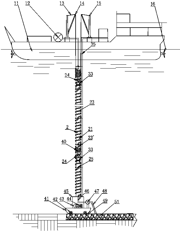
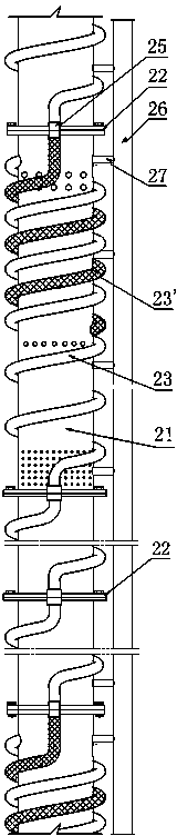
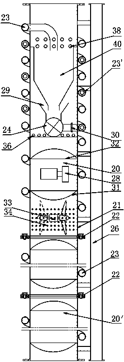
[0015] The length of the total support pipe 2 is based on the design requirements and site construction requirements. The distance between 100 and 1000 meters is a segment of support pipe. The total support pipe is made up of two or more segments of multi-segment support pipe 21, fixedly connected by connecting piece support pipe flange 22 Whole, such as figure 1 , figure 2 Shown.

[0016] The buoyancy air cabins 20, 20' are composed of upper and lower semicircular cover plates 31, baffles 32 and part of the inner wall of the support tube 21. The only difference is the length. The length of the buoyancy air cabin 20 and the buoyancy air cabin 20 can be reduced. The weight of the entire device increases buoyancy, such as image 3 Shown.

[0017] In each section of the support pipe 21 constituting the main support pipe, there are installed two or more buoyancy air cham...


PUM


Abstract

The invention discloses a segmented lifting and conveying device of deep-sea mining annular pipelines. A main supporting pipe is formed by fixing at least two segments of supporting pipes through flanges. An electric hydraulic pump station, a buoyancy air cabin, a boost pump and a hopper are arranged in the main supporting pipe, and an electric power control cable is arranged in a cable groove outside the supporting pipes. The upper end and the lower end of the main supporting pipe are connected with a mining vessel lifting device and a traction steel wire. Conveying pipes are annular pipelines, the front conveying pipes and the rear conveying pipes are arranged on the supporting pipes in a surrounding mode, wherein the front conveying pipes and the rear conveying pipes are disconnected in a front-and-rear mode. The rear conveying pipe and the front conveying pipe of the uppermost segment of the supporting pipe and the lowermost segment of the supporting pipe are connected with an ore sand output pump and a flexible conveying pipe. The upper ends of the rear conveying pipes which are sequentially connected through the supporting pipes are connected with the upper end of the front conveying pipe of the front segment, and the lower ends of the rear conveying pipes are matched with the hopper. An inlet and an outlet of the boost pump are connected with the hopper and the rear conveying pipes. Due to segmented lifting and conveying, the mineral substance free fall gravitational effect is avoided. The lifting distance is longer, the hydraulic pump station reduces the weight of the device under the water and provides power for the boost pump and an all-direction propeller, the supporting pipes are prevented from being twisted and deformed, if blocking occurs, the boost pump reverses to dredge, and the segmented lifting and conveying device of the deep-sea mining annular pipelines is suitable for conveying large-particle mineral substances.

Description

Technical field [0001] The invention relates to a lifting and conveying device for deep-sea mining, in particular to a deep-sea mining annular pipeline segmented lifting and conveying device for conveying deep-water minerals to surface mining ships, which can be widely used in deep-water manganese nodules, mud and many The mining and conveying field of metal ore. Background technique [0002] At present, the known method of pipeline transportation is to transport the minerals collected by the deep-water mining device to the mining ship on the water surface through its transportation pump, transportation hose, ore bin, and rigid lifting pipe. The pipe is transported vertically upwards, so it cannot be transported upwards for long distances. The specific gravity of minerals is larger than that of water, and the specific gravity of various underwater substances is also different. When minerals are transported vertically upwards in the pipeline, the heavier underwater substances will...

Claims


Application Information

Patent Timeline
IPC IPC(8): B65G53/04B65G67/60
Inventor 裘尧云曹健舞谢兴博裘磊博
Owner 裘尧云
Why Eureka
Try Eureka