Sputtering target and organic light-emitting display device including black matrix deposited thereby

A light-emitting display and black matrix technology, applied in the field of sputtering targets, can solve the problems of low contrast ratio, inability to withstand the excimer laser crystallization process, etc., and achieve the effect of low reflectivity and high resistivity

Inactive Publication Date: 2014-02-19
SAMSUNG CORNING PRECISION MATERIALS CO LTD
View PDF6 Cites 7 Cited by
  • Summary
  • Abstract
  • Description
  • Claims
  • Application Information

AI Technical Summary

Problems solved by technology

However, this has the problem of reduced contrast due to stronger reflection of external light from the inner reflective layer
The problem with this is that the organic black matrices in the prior art cannot withstand the crystallization process using an excimer laser
In addition, Cr and Cr oxide (Cr 2 o 3 ) are considered environmental pollutants, making it difficult to still use these materials

Method used


Image

  • Sputtering target and organic light-emitting display device including black matrix deposited thereby

Examples


Embodiment Construction

[0023] Now, the sputtering target according to the present invention and the black matrix deposited therefrom will be described in detail, and embodiments of the present invention are shown in the accompanying drawings and described below, so that those of ordinary skill in the art of the present invention can easily The invention is put into practice.

[0024] Throughout this document, reference should be made to the accompanying drawings, wherein the same reference numbers and symbols are used throughout the different drawings to refer to the same or like components. In the following description of the present invention, detailed descriptions of known functions and components included herein will be omitted when they would make the subject of the present invention unclear.

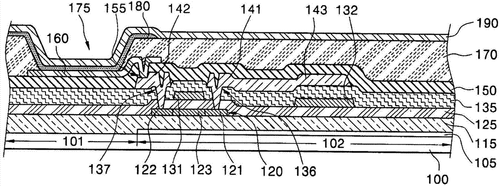
[0025] The sputtering target according to the embodiment of the present invention is used for depositing such as figure 1 The target used in the sputtering process of the black matrix 105 shown in . Su...


PUM

PropertyMeasurementUnit
transmittivityaaaaaaaaaa

Abstract

A sputtering target that can form a black matrix having high-resistance and low-reflection characteristics and an organic light-emitting display device including the black matrix deposited thereby. The sputtering target that is used in a sputtering process for depositing a black matrix contains one selected from the group consisting of Mo-Si-O, W-Si-O and Mo-W-Si-O, the content of the Mo or W being at least 0.5 times the content of the Si.

Description

[0001] This application claims priority from Korean Patent Application No. 10-2012-0089333 filed on Aug. 16, 2012, the entire contents of which are hereby incorporated by reference for all purposes. technical field [0002] The present invention relates to a sputtering target and an organic light-emitting display device including a black matrix deposited through the sputtering target, more specifically, to a sputtering target for forming a black matrix and an organic light-emitting display device including a black matrix deposited through the sputtering target. Organic light-emitting display device with black matrix deposited by sputtering target. Background technique [0003] Generally, an organic light emitting device (OLED) includes an anode, a light emitting layer, and a cathode. When a voltage is applied between the anode and the cathode, holes are injected from the anode into the hole injection layer and then migrate from the hole injection layer to the organic light-e...

Claims


Application Information

Patent Timeline
Patent Type & Authority Applications(China)
IPC IPC(8): C23C14/34C23C14/08H01L27/32
CPCC23C14/3414H01L51/5284C23C14/08H10K59/126H10K50/865H10K71/00H10K71/16
Inventor 韩镇宇金义洙朴承元金珠锡孙仁成
Owner SAMSUNG CORNING PRECISION MATERIALS CO LTD
Why Eureka
Try Eureka