
A W-band impatt diode impedance matching pin and preparation method thereof

An impedance matching and diode technology, applied in the field of millimeter-wave semiconductor devices, can solve the problems of high reliability, low operating voltage, small size, etc., and achieve the effect of improving reliability and enhancing heat dissipation effect.

Active Publication Date: 2016-06-01
EAST CHINA INST OF OPTOELECTRONICS INTEGRATEDDEVICE
View PDF2 Cites 0 Cited by
  • Summary
  • Abstract
  • Description
  • Claims
  • Application Information

AI Technical Summary

Problems solved by technology

[0002] Millimeter wave is a new subject under development. Its operating frequency range is 30-300GHz. It has the characteristics of wide application system bandwidth, small size, light weight, high resolution, and good dynamic effect. It is used in radar, aircraft, and automobile collision avoidance. Radar and automatic cruise control have a wide range of uses; IMPATT diodes have the advantages of large single-tube output power, small size, low operating voltage and high reliability. In the frequency range above 60GHz to 300GHz, millimeter-wave IMPATT diodes have better performance. The application value; the diode pins in the existing low-frequency applications do not have design requirements for matching characteristics, and the pins can withstand low power. For W-band IMPATT diodes, that is, IMPATT diodes that work in the frequency range of 75 ~ 110GHz, cannot direct application

Method used


Image

  • A W-band impatt diode impedance matching pin and preparation method thereof
  • A W-band impatt diode impedance matching pin and preparation method thereof
  • A W-band impatt diode impedance matching pin and preparation method thereof

Examples


Embodiment Construction

[0019] The invention provides a W-band IMPATT diode impedance matching pin:

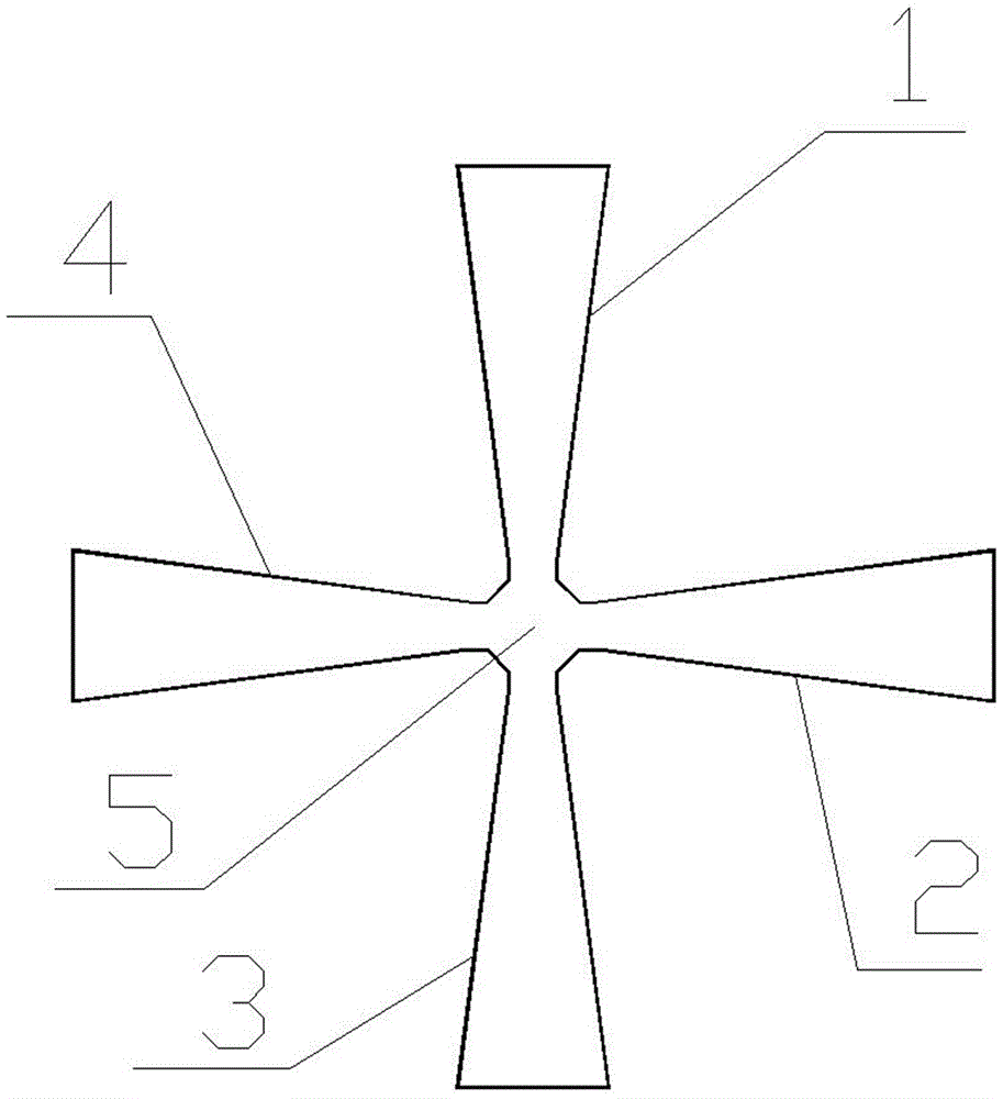
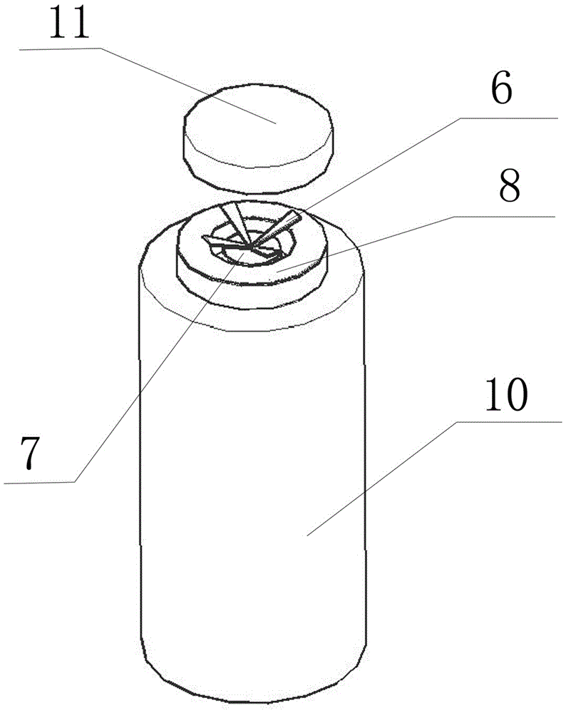
[0020] combine figure 1 and figure 2 As shown, four trapezoidal metal sheets of the same size, the first trapezoidal metal sheet (1), the second trapezoidal metal sheet (2), the third trapezoidal metal sheet (3) and the fourth trapezoidal metal sheet (4) pass through the connecting piece (5) Connect each other to form a cross, with the upper base of each trapezoidal metal sheet facing inward and the lower base facing outward; the connecting sheet (5) is connected to the first trapezoidal metal sheet (1) and the second trapezoidal metal sheet (2) , the third trapezoidal metal sheet (3) and the fourth trapezoidal metal sheet (4) are an integrated structure, which together constitute the impedance matching pin (6); the bottom surface of the connecting sheet (5) and the W-band IMPATT diode (10 ) is fixedly connected to the tube core (7), the lower bottom edge of each trapezoidal metal sheet is fixedly...


PUM


Abstract

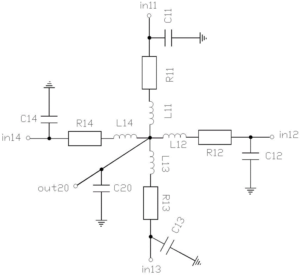
The invention discloses a W-wave-band IMPATT diode impedance matching pin. The W-wave-band IMPATT diode impedance matching pin is in a cross shape formed by mutually connecting four trapezoid metal sheets same in size, the upper bottom edge of each trapezoid metal sheet is inwards arranged, and the lower bottom edge of each trapezoid metal sheet is outwards arranged. The W-wave-band IMPATT diode impedance matching pin further comprises a connecting sheet (5) arranged in the center of the cross shape and connected with the trapezoid metal sheets. The connecting sheet (5) and the four trapezoid metal sheets are of an integrated structure. The bottom face of the connecting sheet (5) is fixedly connected with a diode core (7) of a W-wave-band IMPATT diode (10), and the lower bottom edges of the four trapezoid metal sheets are fixedly connected with a ruby medium ring (8) of the W-wave-band IMPATT diode (10). Lumped equivalent model parameters of the cross-shaped structure formed by the completely-same four trapezoid metal sheets in the W wave band are adopted to be in impedance matching with parameters of the diode core (7) of the W-wave-band IMPATT diode (10), resonance conditions when the W-wave-band IMPATT diode (10) works in a waveguide resonator are met, the heat dissipation effect of the W-wave-band IMPATT diode (10) is improved, and the reliability is improved when the W-wave-band IMPATT diode (10) works under the high power.

Description

technical field [0001] The invention relates to the field of millimeter wave semiconductor devices, in particular to a W-band IMPATT diode impedance matching pin and a preparation method thereof. Background technique [0002] Millimeter wave is a new subject under development. Its operating frequency range is 30-300GHz. It has the characteristics of wide application system bandwidth, small size, light weight, high resolution, and good dynamic effect. It is used in radar, aircraft, and automobile collision avoidance. Radar and automatic cruise control have a wide range of uses; IMPATT diodes have the advantages of large single-tube output power, small size, low operating voltage and high reliability. In the frequency range above 60GHz to 300GHz, millimeter-wave IMPATT diodes have better performance. The application value; the diode pins in the existing low-frequency applications do not have design requirements for matching characteristics, and the pins can withstand low power...

Claims


Application Information

Patent Timeline
Patent Type & Authority Patents(China)
IPC IPC(8): H01L23/49H01L21/48
Inventor 潘结斌陈计学展明浩房立峰朱小燕吕东锋
Owner EAST CHINA INST OF OPTOELECTRONICS INTEGRATEDDEVICE
Learn More