Eureka AIR delivers breakthrough ideas for toughest innovation challenges, trusted by R&D personnel around the world.

Multi-pulse high-voltage triggering device of rotary switch

A rotary switch, high-voltage triggering technology, applied in the field of high-voltage pulse power supply, can solve the problems of long rise time of trigger voltage pulse, unreliable triggering, affecting the reliable triggering of the rotary switch, etc., and achieves improved reliability and stability, light weight and volume. small effect

Inactive Publication Date: 2014-02-19
CHANGCHUN INST OF OPTICS FINE MECHANICS & PHYSICS CHINESE ACAD OF SCI
View PDF5 Cites 9 Cited by
  • Summary
  • Abstract
  • Description
  • Claims
  • Application Information

AI Technical Summary

Problems solved by technology

[0003] In order to solve the existing problems of using a single high-voltage pulse to trigger the rotary switch, the trigger voltage pulse rise time is long, the trigger is unreliable, and the reliable trigger and high repetition frequency operation of the rotary switch are affected. The invention provides a trigger pulse voltage with a short rise time. , Trigger safe and reliable rotary switch multi-pulse high-voltage trigger device

Method used


Image

  • Multi-pulse high-voltage triggering device of rotary switch
  • Multi-pulse high-voltage triggering device of rotary switch
  • Multi-pulse high-voltage triggering device of rotary switch

Examples


Embodiment Construction

[0029] The present invention will be further described in detail below in conjunction with the drawings.

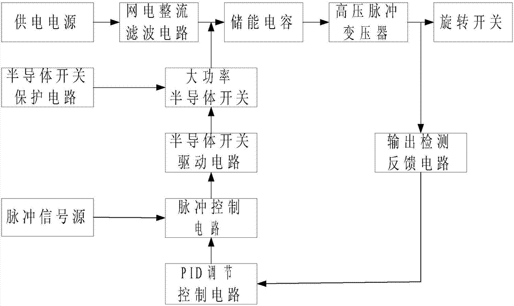
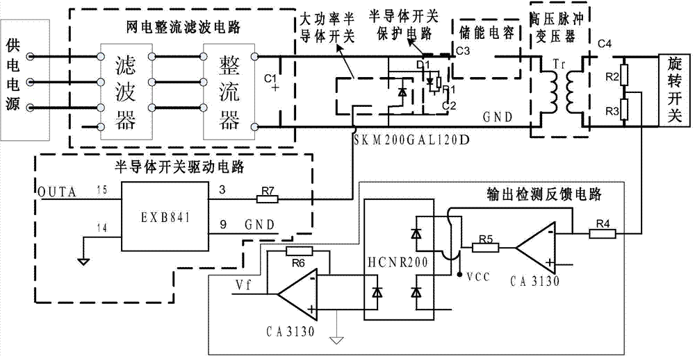
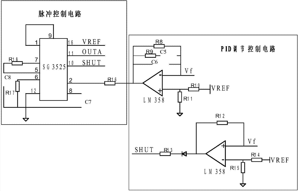
[0030] Such as figure 1 As shown, the rotary switch multi-pulse high-voltage trigger device of the present invention consists of a power supply outputting three-phase alternating current, a network power rectification filter circuit electrically connected to the power supply, a pulse signal source, a pulse control circuit electrically connected to the pulse signal source, A semiconductor switch drive circuit electrically connected to the pulse control circuit, a high-power semiconductor switch electrically connected to the semiconductor switch drive circuit, a semiconductor switch protection circuit electrically connected to the high-power semiconductor switch, and a grid power rectifier filter circuit and a high-power semiconductor switch, respectively It consists of an electrically connected energy storage capacitor, a high voltage pulse transformer electrically connected t...


PUM


Abstract

The invention discloses a multi-pulse high-voltage triggering device of a rotary switch, and relates to the field of high-voltage pulse power sources. The problems that a rotary switch is triggered through a single high-voltage pulse in the prior art, the triggering voltage pulse rise time is long, and triggering is not reliable are solved. The multi-pulse high-voltage triggering device is composed of a grid electricity rectifying filtering circuit, a pulse signal source, a pulse control circuit, a semiconductor switch drive circuit, a high-power semiconductor switch, a semiconductor switch protection circuit, an energy storing capacitor, a high-voltage pulse transformer, an output detection feedback circuit and a PID regulation control circuit, wherein the grid electricity rectifying filtering circuit is electrically connected with a power supply, the pulse control circuit is electrically connected with the pulse signal source, the semiconductor switch drive circuit is electrically connected with the pulse control circuit, the high-power semiconductor switch is electrically connected with semiconductor switch drive circuit, the semiconductor switch protection circuit is electrically connected with the high-power semiconductor switch, the energy storing capacitor is respectively and electrically connected with the grid electricity rectifying filtering circuit and the high-power semiconductor switch, the high-voltage pulse transformer is electrically connected with the energy storing capacitor, the output detection feedback circuit is electrically connected with the high-voltage pulse transformer, and the PID regulation control circuit is electrically connected with the output detection feedback circuit. According to the multi-pulse high-voltage triggering device, the triggering pulse rise time is smaller than 10 microseconds, and triggering is reliable and stable.

Description

Technical field [0001] The invention relates to the technical field of high-voltage pulse power supplies, in particular to a rotary switch multi-pulse high-voltage trigger device. Background technique [0002] The rotary switch is a high-voltage spark gap switch. In order to make it conduct reliably, it needs to be triggered by a high-voltage trigger pulse. At present, the trigger pulse device of the rotary switch is mostly triggered by a single high-voltage pulse, and the trigger pulse voltage rise time is longer, reaching hundreds of microseconds. Because the gas inside the rotary switch flows out at a high speed, the ionized gas concentration generated by a single high-voltage trigger pulse is very easy to change from The internal flow of the rotary switch makes it difficult to turn on the rotary switch; the long rise time of the trigger pulse voltage will cause serious jitter in the conduction of the rotary switch, and the conduction dispersion is large, and it seriously affe...

Claims


Application Information

Patent Timeline
Patent Type & Authority Applications(China)
IPC IPC(8): H02M9/06
Inventor 郭立红张兴亮孟范江
Owner CHANGCHUN INST OF OPTICS FINE MECHANICS & PHYSICS CHINESE ACAD OF SCI
Why Eureka
Eureka Blog
Learn More