Horizontal and vertical feed burr-free bar cutting device

A cutting device, burr-free technology, used in positioning devices, feeding devices, clamping and other directions, can solve the problem of inability to cut with solid bars, and achieve the effect of saving cutting time, uniform cutting and good product quality

Active Publication Date: 2014-02-26
浙江安统汽车部件有限公司
View PDF7 Cites 19 Cited by
  • Summary
  • Abstract
  • Description
  • Claims
  • Application Information

AI Technical Summary

Problems solved by technology

In order to cut the pipe fittings and make the pipe mouth free of burrs, deformation and shrinkage, a mandrel is insert

Method used


Image

  • Horizontal and vertical feed burr-free bar cutting device
  • Horizontal and vertical feed burr-free bar cutting device
  • Horizontal and vertical feed burr-free bar cutting device

Examples


Embodiment 1

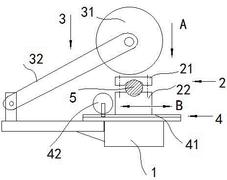
[0029] Embodiment 1: as figure 1 As shown, a burr-free bar cutting device with vertical and horizontal feeds includes a machine base 1, an upper cutter mechanism connected to the machine base 1, and a bar clamping mechanism 2 arranged longitudinally along the machine base 1. The upper cutter The mechanism includes an upper cutter frame 3 hinged with the machine base 1, the upper cutter frame 3 is equipped with a main motor and an upper cutter 31, and a joystick is connected to the movable end of the upper cutter frame 3; The following cutter mechanism is arranged below the knife mechanism, and the lower cutter mechanism includes a guide rail 41 arranged laterally along the machine base 1, and the lower cutter frame 4 is slidably connected on the guide rail 41, and the lower cutter motor is installed on the lower cutter frame 4. And following cutter 42, following cutter rest 4 is driven by the transmission mechanism that is connected on the support 1.

[0030] figure 1 Th...

Embodiment 2

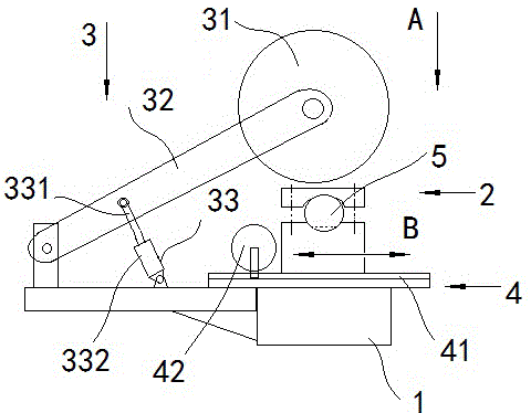
[0032] Embodiment 2: The upper cutter frame 3 is hinged with the machine base 1 through the swing arm 32, the middle part of the swing arm 32 is pinned to the piston rod 331 of the swing arm oil cylinder 33, and the cylinder body 332 of the swing arm oil cylinder 33 is hinged with the machine base 1. The piston rod of the swing arm oil cylinder 33 drives the swing arm of the upper cutter holder, so that the upper cutter is pressed to the bar material 5, and the feed force of the upper cutter 31 is provided, as figure 2 shown.

Embodiment 3

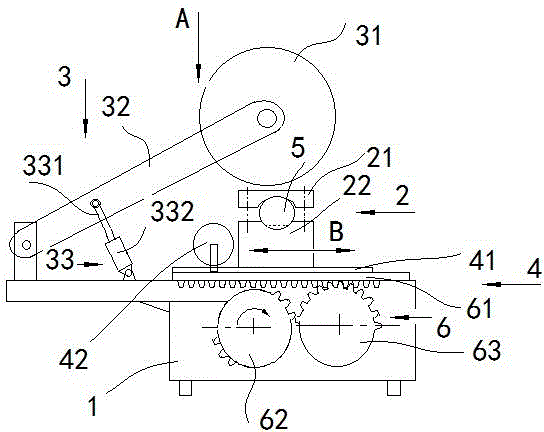
[0033]Embodiment 3: The transmission mechanism that drives the lower cutter frame to move is composed of a rack and pinion transmission mechanism, the rack is fixedly connected to the lower side of the lower cutter frame, the gear shaft is connected to the frame through a bearing, and the motor is connected to the gear shaft through a speed change mechanism For the control of the motor, the conventional method is used, and the motor can be rotated forward or reversely with a changeover switch, and the cutter head is moved forward or reversed in the corresponding direction, and the rest of the structure is the same as that of embodiment 1 or embodiment 2.


PUM


Abstract

The invention discloses a horizontal and vertical feed burr-free bar cutting device, and provides a double-cutter horizontal and vertical bar cutting device to overcome the defect that a workpiece directly cut by a single cutter of a bar cutting machine in the prior art always has burrs. The horizontal and vertical feed burr-free bar cutting device comprises a base, an upper cutter mechanism and a bar clamping mechanism, the upper cutter mechanism is connected onto the base, the bar clamping mechanism is vertically arranged along the base, the upper cutter mechanism comprises an upper cutter frame hinged to the base, a main motor and an upper cutter are mounted on the upper cutter frame, a lower cutter mechanism positioned below the upper cutter mechanism is arranged on the base and comprises a guide rail horizontally arranged along the base, a lower cutter frame is slidably connected onto the guide rail, a lower cutter motor and a lower cutter are mounted on the lower cutter frame, and the lower cutter frame is driven by a transmission mechanism connected on the base. The burr-free bar cutting device has the advantages that the device is provided with a vertical cutting mechanism and a horizontal cutting mechanism, the burrs are avoided, automatic control can be realized, bars are rapidly cut and are fine in quality, and labor and time are saved.

Description

technical field [0001] The invention belongs to the technical field of cutting machines, and in particular relates to a burr-free bar cutting machine. Background technique [0002] Most of the bar cutting machines in the prior art use the cutting blade to cut the bar from top to bottom after clamping the bar. The cutting knife is a disc-shaped blade or a long strip saw blade; A certain downward pressure needs to be applied. When the cutting is about to be completed, there is only a thin layer of skin left on the lower side of the bar. The strength of this thin layer of material is not enough to withstand the downward pressure of the cutting blade. The pressure causes the skin to be broken before it is cut off, and becomes a burr connected to the end surface of the workpiece; in order to avoid the occurrence of burrs, it is necessary to innovate the cutting machine. [0003] For example, China Patent Application No. 200910144550.X, an invention patent named "Pipe Chiple...

Claims


Application Information

Patent Timeline
IPC IPC(8): B23D79/00B23Q5/34B23Q3/06B23Q7/00
Inventor 李仪平沃春耀
Owner 浙江安统汽车部件有限公司
Why Eureka
Try Eureka