
Real-time monitoring device for welding robot welding process

A welding robot and real-time monitoring technology, applied in welding protection devices, welding equipment, welding accessories, etc., can solve the problems of low work efficiency, inability to independently obtain workpiece positioning information, welding seam space position information, etc., and achieve simple and convenient structure. Flexible, easy-to-use effects

Active Publication Date: 2014-02-26
SHANGHAI UNIV OF ENG SCI
View PDF6 Cites 25 Cited by
  • Summary
  • Abstract
  • Description
  • Claims
  • Application Information

AI Technical Summary

Problems solved by technology

Because the welding robot has the advantages of strong versatility and reliable work, but it cannot independently obtain workpiece positioning information, weld space position information, weld penetration information, etc. When the welding object changes, it needs to re-teach and cause low work efficiency. In the welding process, it is the development trend of welding robots to realize the automation and intelligence of welding, and realize the identification, positioning and tracking of welding seam information.

Method used


Image

  • Real-time monitoring device for welding robot welding process
  • Real-time monitoring device for welding robot welding process
  • Real-time monitoring device for welding robot welding process

Examples


Embodiment Construction

[0022] The technical solutions of the present invention will be further described below in conjunction with the accompanying drawings and embodiments.

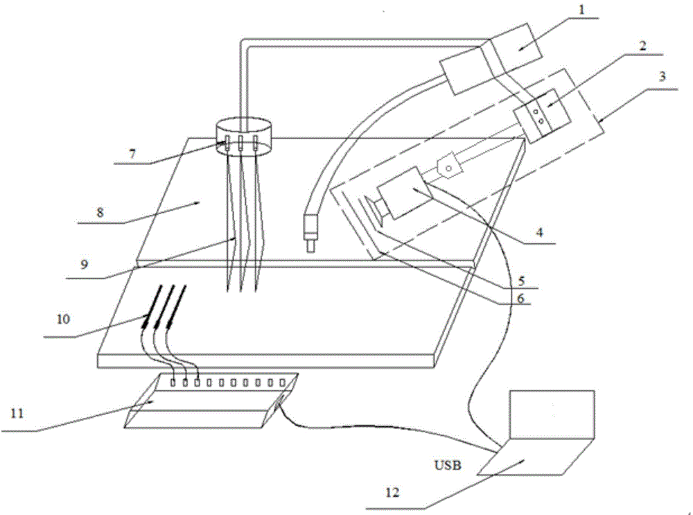
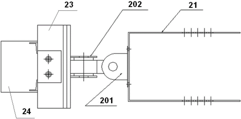
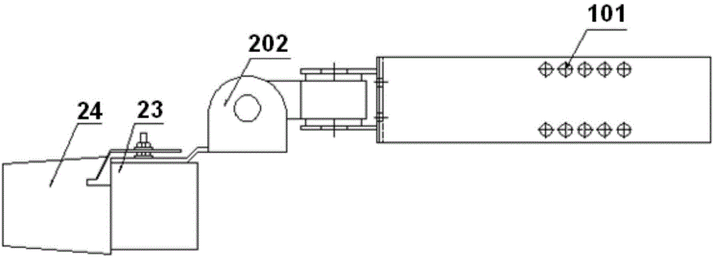
[0023] see figure 1 , figure 2 , image 3 , Figure 4 , Figure 5 A real-time monitoring device for the welding process of a welding robot shown includes a welding torch 1, an image acquisition mechanism 3, a laser emission mechanism and a temperature acquisition mechanism. The image acquisition mechanism 3 and the laser emission mechanism are fixed on the welding torch, so that the image acquisition The mechanism and the laser emitting mechanism move synchronously with the movement of the welding torch. The image acquisition mechanism includes a U-shaped frame 21 and a CCD camera 4. One end of the U-shaped frame 21 is fixedly connected with the welding torch 1 through a connecting rod 2, and the other end of the U-shaped frame 21 Connected to the CCD camera through the azimuth adjustment mechanism,

[0024] Two rows of ...


PUM


Abstract

The invention discloses a real-time monitoring device for a welding robot welding process. The device comprises a welding gun, an image collection mechanism, a laser transmitting mechanism and a temperature collection mechanism. The image collection mechanism and the laser transmitting mechanism are fixedly arranged on the welding gun. The image collection mechanism comprises a U-shaped support and a charge coupled device (CCD) camera, an aluminum sleeve is arranged on the outside of a machine body of the CCD camera, and a copper foil is coated on the inner lateral wall of the aluminum sleeve. A copper sleeve is arranged on the outside of a lens, and a plastic filler is arranged between the lens and the copper sleeve. The laser transmitting mechanism comprises an aluminum column and an end cover. A laser light-emitting diode is arranged in the aluminum column. The temperature collection mechanism comprises a plurality of thermocouples arranged evenly at intervals and a data collection module. The data collection module and the CCD camera are connected onto an industrial personal computer through universal serial bus (USB) transmission lines respectively. By means of a laser beam transmitted by the laser light-emitting diode and the CCD camera, active vision sensing can be achieved, and fusion processing and monitoring of collection data of temperature and subjective vision are achieved through the industrial personal computer.

Description

technical field [0001] The invention relates to the field of welding robots, and more specifically relates to a real-time monitoring device for the welding process of a welding robot. Background technique [0002] The integration of robot and sensing technology is a rapidly developing application technology, its own development is inseparable from its application in various fields, its own development will certainly expand the depth of its application, and at the same time in each application field The proposed requirements will also greatly promote the development of robots and sensing technologies, and the integration of different sensing technologies will become the direction of future development. Because the welding robot has the advantages of strong versatility and reliable work, but it cannot independently obtain workpiece positioning information, weld space position information, weld penetration information, etc. When the welding object changes, it needs to re-teach ...

Claims


Application Information

Patent Timeline
Patent Type & Authority Applications(China)
IPC IPC(8): B23K9/095
CPCB23K9/0956B23K9/1274B23K9/321
Inventor 曹晓莲马丁王臻杰蒋天颖徐培全
Owner SHANGHAI UNIV OF ENG SCI
Learn More