Regenerative industrial furnace and convection radiation wall thereof

An industrial furnace and regenerative technology, applied in furnaces, furnace components, lighting and heating equipment, etc., can solve the problem of uneven resistance of different airflow channels, uneven distribution of flame and high-temperature furnace gas, and poor mixing of fuel and combustion-supporting air To achieve the effect of improving fluidity and medium mixing uniformity, improving heat transfer effect, improving production efficiency and economic benefits

Active Publication Date: 2014-02-26
宝武集团中南钢铁有限公司 +1
View PDF6 Cites 0 Cited by
  • Summary
  • Abstract
  • Description
  • Claims
  • Application Information

AI Technical Summary

Problems solved by technology

Regenerative industrial furnaces generally adopt intermittent furnace side smoke exhaust and pulse combustion, so furnace pressure fluctuations are prone to occur; at the same time, due to the different degrees of rupture and hardening of the regenerators in different regenerators during operation, It affects the smoke exhaust resistance and the change of wind pressure, so that the resistance of different airflow channels on both sides is also uneven; therefore, the high-temperature furnace gas in the regenerative industrial furnace is no longer mainly due to the uneven distribution of the traditional heating furnace along the length of the furnace , but at the same time, the pressure along the furnace width direction is also unevenly distributed, and the fluctuation of furnace pressure from near to far from the furnace mouth increases, which further causes the uneven distribution of flame and high-temperature furnace gas in the furnace
[0003] At present, due to the above reasons, most regenerative heating furnaces have the following problems: the fuel and combustion air are not well mixed, the combustion medium and high-temperature furnace gas are directly sucked away by the opposite smoke exhaust furnace mouth, and the flames are in multiple directions in the furnace. The heat is not fully released. According to the thermal test, there are relatively high combustible components and oxygen in the flue gas at the same time.
It is manifested in production: one is high energy consumption, and the other is uneven heating of workpieces in the furnace

Method used


Image

  • Regenerative industrial furnace and convection radiation wall thereof
  • Regenerative industrial furnace and convection radiation wall thereof
  • Regenerative industrial furnace and convection radiation wall thereof

Examples


Embodiment Construction

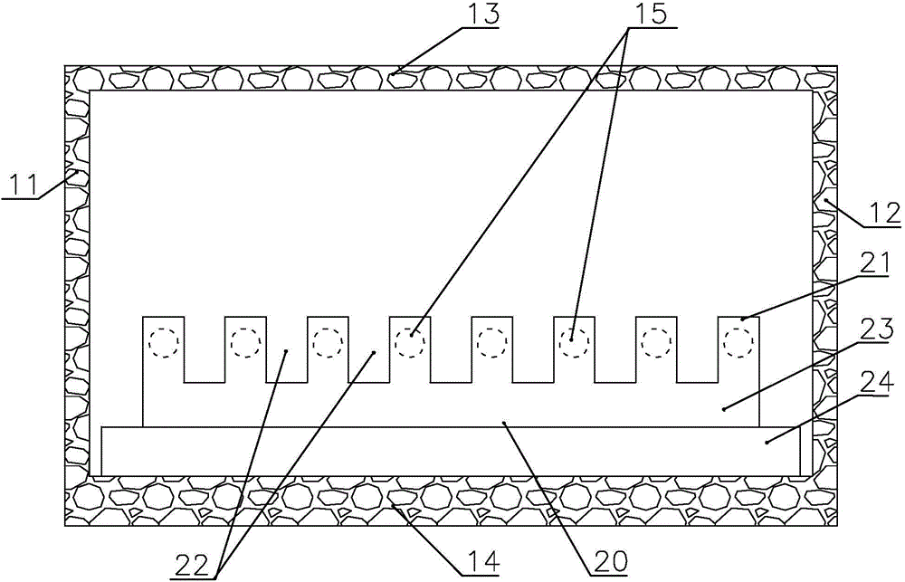
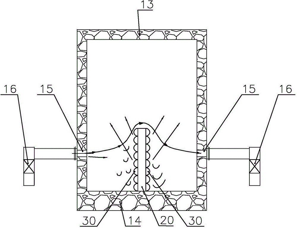
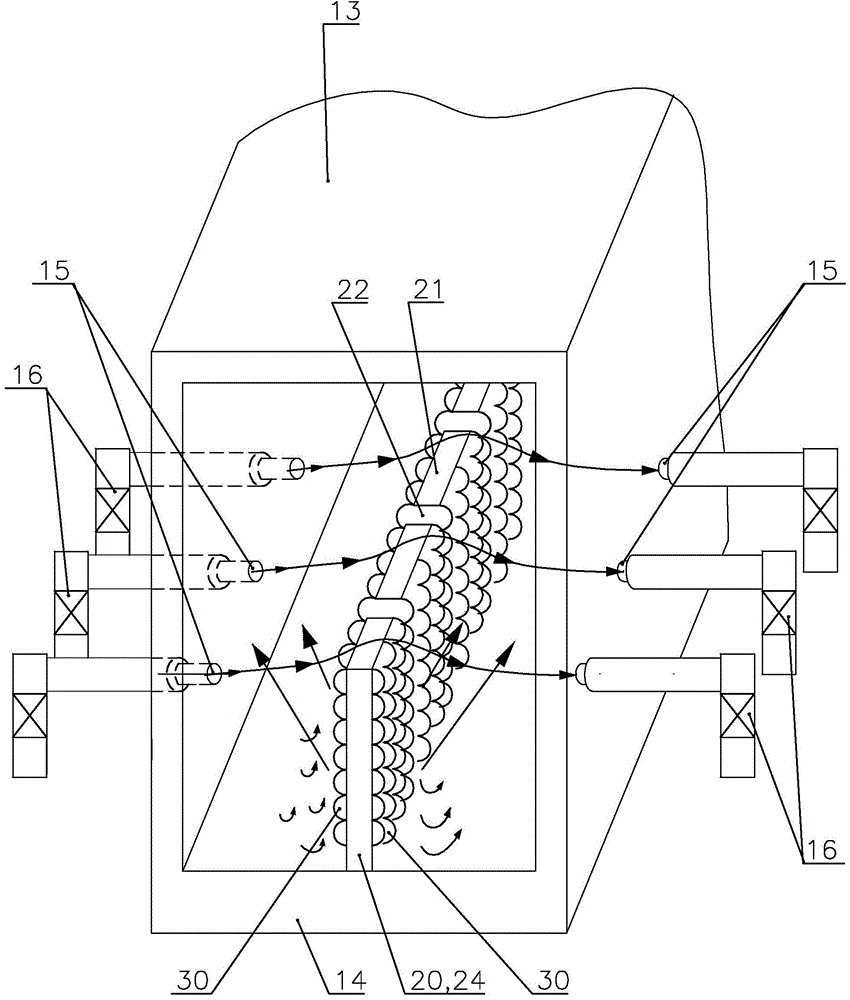
[0029] Such as Figure 1-6 , which are structural schematic diagrams of different viewing angles of the embodiment of the regenerative industrial furnace and the convective radiation wall of the present invention, respectively. The regenerative industrial furnace embodiment includes a front end 11 of a furnace body, a rear end 12 of a furnace body, a furnace top 13, a furnace bottom 14, and two sides each having eight furnace ports 15, and the furnace ports on both sides correspond one by one. The furnace openings on the sides are all connected with waste heat regenerators 16; a convective radiation wall 20 is provided in the middle of the furnace width between the regenerative industrial furnace 2 sides; direction.

[0030] The convective radiation wall 20 is made of high temperature resistant material, and it is located in the middle of the furnace width of the regenerative industrial furnace that has more than two furnace ports on both sides and the furnace ports on both s...


PUM


Abstract

The invention relates to a regenerative industrial furnace and a convection radiation wall thereof. The convection radiation wall made of a high-temperature-resistant material is located between two-side furnace mouths and comprises hill-type protruding peaks, valleys among the peaks, a foothill below the valleys and a base below the foothill. The peaks have height and width capable of blocking direct airflow between the two-side furnace mouths, more than two hemispheres are regularly distributed on wall surfaces of the two-side furnace mouths face to face on two sides of the convection radiation wall, the diameter and height of each hemisphere is 15-50mm, and spacing between peaks of the hemispheres is 1-2 times the diameter of each hemisphere which accounts for 35-80% of the wall surface per unit. By the convection radiation wall made of a wall structure and the material which can improve heat transfer effect of convention radiation, convection and radiation heat transfer of high-temperature furnace gas in the furnace can be increased, media mixing and flue gas flow in the furnace can be improved, heating uniformity of workpieces can be improved, heating energy consumption can be lowered, and heat efficiency of a hearth can be improved.

Description

technical field [0001] The present invention relates to a regenerative industrial furnace and its equipment. More specifically, the present invention relates to a regenerative industrial furnace and the flow disturbance and heat transfer equipment in the furnace. Background technique [0002] At present, the regenerative industrial furnace is a new type of industrial furnace that uses the external regenerators on both sides to preheat the combustion air or preheat the gas fuel at the same time to achieve high temperature air combustion. Regenerative industrial furnaces generally adopt intermittent furnace side smoke exhaust and pulse combustion, so furnace pressure fluctuations are prone to occur; at the same time, due to the different degrees of rupture and hardening of the regenerators in different regenerators during operation, It affects the smoke exhaust resistance and the change of wind pressure, so that the resistance of different airflow channels on both sides is als...

Claims


Application Information

Patent Timeline
Patent Type & Authority Applications(China)
IPC IPC(8): F27D1/00
Inventor 罗国民李国权曾向昌朱海洋丁克温志红杨宇
Owner 宝武集团中南钢铁有限公司
Why Eureka
Try Eureka