Temperature measurement method and temperature measurement system using optical fiber sensing technology

An optical fiber sensing technology and optical fiber sensor technology, which are applied in the directions of thermometers, thermometers, and measuring devices with physical/chemical changes, can solve the problems of aging of battery packs, complex signal wiring, and susceptibility to electromagnetic environment interference. Achieving the effect of guaranteeing the quality of life and preventing the impact

Active Publication Date: 2014-02-26
STATE GRID CORP OF CHINA +3
View PDF5 Cites 5 Cited by
  • Summary
  • Abstract
  • Description
  • Claims
  • Application Information

AI Technical Summary

Problems solved by technology

However, since each energy storage battery pack currently used is composed of multiple lithium battery cells connected in series and parallel, the imbalance between the cells is the main reason for the aging of the battery pack, and the thermistor is usually used to monitor only the temperature of the entire battery pack. In some points, instead of monitoring each battery cell, usually there are about 2-4 thermistors in an energy storage battery pack, which reflect very limited internal temperature distribution of the energy storage battery pack, which is far from meeting the requirements of battery cell monitoring; And the thermistor is an electrical signal sensor, which is easily disturbed by the electromagnetic environment; if there are too many, the signal wiring is also complicated, which limits the application of the thermistor method to a certain extent, so a more advanced energy storage is required Battery pack temperature measurement method to solve the above problems

Method used


Image

  • Temperature measurement method and temperature measurement system using optical fiber sensing technology
  • Temperature measurement method and temperature measurement system using optical fiber sensing technology
  • Temperature measurement method and temperature measurement system using optical fiber sensing technology

Examples


Embodiment Construction

[0015] The technical means adopted by the present invention to achieve the intended invention purpose are further described below in conjunction with the drawings and preferred embodiments of the present invention.

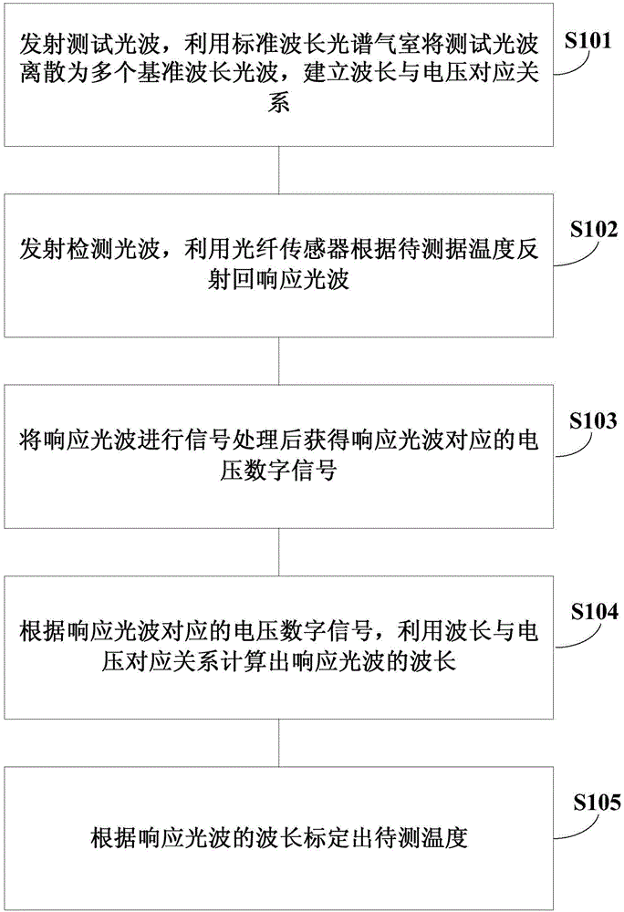
[0016] figure 1 It is a flowchart of a temperature measurement method using optical fiber sensing technology according to an embodiment of the present invention. like figure 1 As shown, the methods shown include:

[0017] Step S101, emitting test light waves, discretizing the test light waves into a plurality of reference wavelength light waves by using a standard wavelength spectrum gas cell, and establishing a corresponding relationship between wavelength and voltage.

[0018] Step S102 , emitting a detection light wave, and using the optical fiber sensor to reflect back a response light wave according to the temperature to be measured.

[0019] Step S103, after signal processing is performed on the response light wave, a voltage digital signal corresponding ...


PUM


Abstract

The invention relates to a temperature measurement method and a temperature measurement system using an optical fiber sensing technology. The method comprises the following steps: emitting a test optical wave, using a standard wavelength spectrum air chamber to disperse the test optical wave into a plurality of reference-wavelength optical waves and establishing a corresponding relationship between wavelength and voltage; emitting a detection optical wave and using an optical fiber sensor to reflect a response optical wave back according to temperature to be measured; carrying out signal processing on the response optical wave to obtain a voltage digital signal corresponding to the response optical wave; making use of the corresponding relationship between wavelength and voltage to calculate the wavelength of the response optical wave according to the voltage digital signal corresponding to the response optical wave; and calibrating the temperature to be measured according to the wavelength of the response optical wave.

Description

technical field [0001] The invention relates to a temperature measurement method and system using optical fiber sensing technology, which is mainly used in energy storage lithium battery packs. Background technique [0002] Optical fiber sensing technology is a new type of sensing technology that uses light as the carrier and optical fiber as the medium to perceive and transmit external signals, which has developed rapidly along with the development of optical fiber and optical fiber communication technology. Fiber Bragg grating sensor is a functional optical fiber sensor using Bragg grating as a sensitive element. Its sensing principle is to use the photosensitivity of optical fiber materials to form a spatial phase grating in the fiber core with spatial interference fringes of ultraviolet light. Reflect the influence of the central wavelength of the Bragg grating to reversely detect the external physical value. There are two physical quantities that affect the central wav...

Claims


Application Information

Patent Timeline
Patent Type & Authority Applications(China)
IPC IPC(8): G01K11/32G01K11/3206
Inventor 刘少宇陈豪李娜祝翔白恺刘辉李智朱斯石世前宋堃
Owner STATE GRID CORP OF CHINA
Why Eureka
Try Eureka