Measuring device and measuring method for dynamic contact resistors of conductive devices

A technology of dynamic contact resistance and conductive devices, which is applied in the direction of measuring devices, measuring resistance/reactance/impedance, measuring electrical variables, etc., can solve the problems that the measurement channel cannot meet the test ring number requirements of conductive devices, is inconvenient to carry, and is bulky, etc. It achieves the effects of being easy to carry out for testing, intuitive display results, and high measurement accuracy

Active Publication Date: 2014-02-26
SHAANXI AEROSPACE TIMES NAVIGATION EQUIP CO LTD
View PDF6 Cites 20 Cited by
  • Summary
  • Abstract
  • Description
  • Claims
  • Application Information

AI Technical Summary

Problems solved by technology

[0006] (b). One measurement can only realize the test of 38 rings of the conductive device. The conductive device with more than 38 rings needs to manually exchange the cable plug, which can be completed through multiple measurements. For example, the 96-ring conductive device needs to be measured four times. Finish;
[0007] (c). The number of measurement channels cannot meet the requirements for the number of test rings required by the conductive device, and the operation of exchanging cable plugs cannot be performed when performing sound vibration, vibration and other test items, and the data collection and monitoring of all slip rings of the conductive device cannot be realized;
[0008] (d). The measured data needs to be manually copied and pasted and calculated, and it is impossible to set test parameters and automatically generate reports;
[0009] (e). The existing dynamic contact resistance tester consists of several independent parts, which are bulky and need to be connected to each other to form a system, which is extremely inconvenient to carry when going out for testing

Method used


Image

  • Measuring device and measuring method for dynamic contact resistors of conductive devices
  • Measuring device and measuring method for dynamic contact resistors of conductive devices
  • Measuring device and measuring method for dynamic contact resistors of conductive devices

Examples


Embodiment Construction

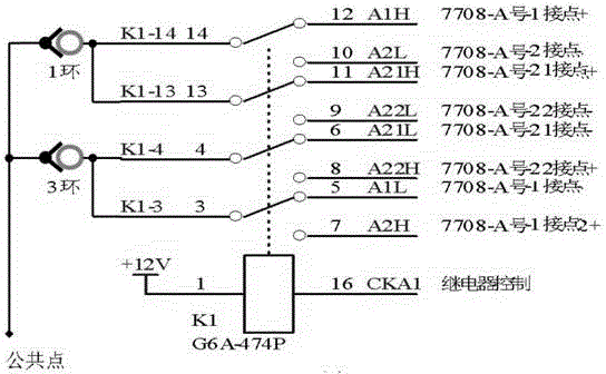
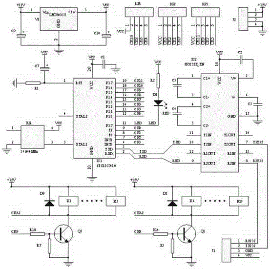
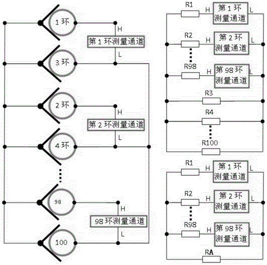
[0038] exist figure 1 In the embodiment shown in -7, the chassis is designed with an upper clamshell structure. When the clamshell is opened, the front is a 17-inch industrial LCD screen. The upper layer of the chassis is equipped with an AC220V power switch, an LCD screen setting switch, USB1, USB2 ports, and a laptop with a mouse. The integrated keyboard (5), the middle layer of the chassis is installed with the main board of the industrial computer, the hard disk, the LCD driver board, the system power supply (6), the transfer control module (4), etc., and the bottom layer of the chassis is a multi-channel micro-resistance measurement unit (2) ;The rear panel of the chassis is equipped with a cooling fan, X1~X4 interface sockets, USB3, USB4 interface sockets, RJ45 network cable interface sockets, safety ground terminals and AC220V power sockets, and the X1~X4 interface sockets pass the test connection cable (8) and the tested conductive device (7) is connected. The industr...


PUM


Abstract

A measuring device and a measuring method for dynamic contact resistors of conductive devices are disclosed. The invention provides a special-purpose measuring device for accurately measuring dynamic and static contact resistors which are applied to conductive devices in a variety of models in the aviation and aerospace field. The measuring device comprises a liquid crystal display, an industrial control computer system, a multipath micro resistor measurement unit, a switch control module, a keyboard, a mouse, a system power supply, a test connection cable, conductive devices to be measured and the like. According to the invention, dynamic and static contact resistors between conducting rods and electric brushes of conductive devices in a variety of models such as 96 rings, 76 rings, 60 rings, 54 rings and the like can be accurately measured, parameters such as the measuring ring number, the measuring mode, the measuring number of times and the like of the conductive devices can be set, and functions such as automatic sampling, storage, processing of measured data, and report generation, historical data query and the like are achieved.

Description

technical field [0001] The invention provides a special equipment for accurate testing of dynamic and static contact resistance of various types of conductive slip rings used in aviation and aerospace, and belongs to the technical field of multi-channel electrical parameter signal measurement and control. Background technique [0002] Conductive device, also called power transmission device, is a precision power transmission device that realizes signal and current transmission between two relative rotating mechanisms. Applications where unrestricted, continuous or intermittent rotation is required while transferring power or data from a fixed position to a rotating position. The variation of dynamic contact resistance is a key parameter index of the conductive device during the test process. It refers to the maximum variation of the contact resistance when the brush and the ring rotate relative to each other, expressed as the difference between the maximum value and the mini...

Claims


Application Information

Patent Timeline
Patent Type & Authority Applications(China)
IPC IPC(8): G01R27/02
Inventor 周革平王英锋
Owner SHAANXI AEROSPACE TIMES NAVIGATION EQUIP CO LTD
Why Eureka
Try Eureka