A cold cathode electron gun modulated by microwave

An electron gun and cold cathode technology, which is applied in the field of electron guns, can solve problems such as filament breakage or short circuit, high cost, and high cathode temperature

Inactive Publication Date: 2016-02-03
UNIV OF ELECTRONICS SCI & TECH OF CHINA
View PDF4 Cites 0 Cited by
  • Summary
  • Abstract
  • Description
  • Claims
  • Application Information

AI Technical Summary

Problems solved by technology

The electron gun components in the above-mentioned electric vacuum radiation source devices occupy a pivotal position. The electron guns in traditional electric vacuum radiation source devices generally use a thermal emission cathode system. After decades of development, the thermal emission cathode process has been very mature and is widely used in Among all kinds of electric vacuum radiation source devices, the thermal emission cathode has the following significant disadvantages: complex structure, high cost, and the cathode system is composed of various metal and ceramic components. Since the hot cathode works in a high temperature environment of thousands of degrees, the heating in the cathode The filament used is easy to break or short circuit, resulting in damage to the device; on the other hand, because it takes a long time to heat up during operation, it not only increases the complexity of the system, but also reduces the system efficiency; One of the main reasons why radiation source devices are difficult to integrate
Therefore, this type of cold cathode electron gun is not suitable for integrated miniature electric vacuum radiation source devices, and can only be used for devices such as cold cathode electric light sources, pixel tubes (displays), etc., whose electron injection frequency is much lower than microwave frequencies.

Method used


Image

  • A cold cathode electron gun modulated by microwave
  • A cold cathode electron gun modulated by microwave
  • A cold cathode electron gun modulated by microwave

Examples


Embodiment Construction

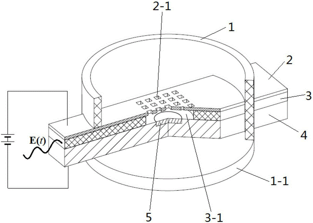
[0013] Take the cold-cathode electron gun used for the miniature electric vacuum radiation source in the 3mm frequency band as an example: the electron gun shell 1 has an inner diameter of φ5mm, an outer diameter of φ7mm, and a height of 5mm, and the material is 99 # Ceramic, its lower end is sealed with the base 1-1, and its upper end is connected with the resonant system to form a sealed vacuum chamber when in use, and the vacuum degree can reach 10 -5 Pa. The electron gun core composed of the microwave input layer 3, the lower electrode plate 4, its cold cathode 5, and the upper electrode plate 2 traverses the electron gun housing 1, and the electron injection and output holes 2-1 are placed at the axial position of the inner cavity of the housing, and the two ends are respectively Stretch out of the shell, seal and fix the base 1-1 and the electron gun shell 1 into one body through the lower electrode plate 4, both sides of the gun core and the top surface of the upper ele...


PUM


Abstract

The invention belongs to the cold-cathode electron gun used for supporting vacuum radiation source devices, including the electron gun shell and its base, an upper electrode plate, a lower electrode plate and a cold cathode with arrayed electron injection and output holes, and a plate between the upper and lower electrode plates. Microwave input layer with interaction cavity. In the cold cathode electron gun, a microwave input layer is added between the upper and lower electrode plates of the traditional cold cathode electron gun, and a cavity is set above the cold cathode in the middle section of the microwave input layer as an interaction cavity, and the cold cathode is embedded in the interaction cavity. At the bottom of the cavity, the upper electrode plate is facing the interaction cavity, and a group of arrayed electron injection and output holes whose size is smaller than the microwave wavelength is opened; therefore, the injection wave interaction cavity has small space, low power consumption, integration, small size, The response speed is fast, and microwaves of different frequencies can be fed in according to requirements to adjust the emission current of cold cathodes to generate electron beams of different frequencies and intensities, provide electron emission sources for micro-electric vacuum devices, and effectively expand the scope of application.

Description

technical field [0001] The invention relates to an electron gun which can be integrated into an electric vacuum radiation source device, in particular to a cold-cathode electron gun which can adjust the frequency of feeding microwaves to generate electron beams with different modulation frequencies. Background technique [0002] As an indispensable core device of military electronic systems such as radar, electronic countermeasures, and space communication, microwave electric vacuum radiation source devices have been widely valued. The electron gun components in the above-mentioned electric vacuum radiation source devices occupy a pivotal position. The electron guns in traditional electric vacuum radiation source devices generally use a thermal emission cathode system. After decades of development, the thermal emission cathode process has been very mature and is widely used in Among all kinds of electric vacuum radiation source devices, the thermal emission cathode has the f...

Claims


Application Information

Patent Timeline
Patent Type & Authority Patents(China)
IPC IPC(8): H01J29/48
Inventor 袁学松鄢扬
Owner UNIV OF ELECTRONICS SCI & TECH OF CHINA
Why Eureka
Try Eureka