Small circularly-polarized antenna

A circularly polarized antenna, small-scale technology, applied in the field of RFID applications, can solve problems affecting antenna performance indicators, reduce antenna efficiency, etc., to simplify installation, save costs, and overcome the effects of narrow bandwidth

Inactive Publication Date: 2014-02-26
深圳市博纬智能识别科技有限公司
View PDF5 Cites 10 Cited by
  • Summary
  • Abstract
  • Description
  • Claims
  • Application Information

AI Technical Summary

Problems solved by technology

[0004] However, there are many deficiencies in the methods currently used, which will affect other performance indicators of the antenna.
For example, the use of short-circuit probe loading, while reducing the size of the antenna, will also bring some disadvantages: on the one hand, the impedance matching depends on the position of the short-circuit probe and the distance from its feeding point, which imposes strict requirements on manufacturing tolerances ; On the other hand, it is the problem of bandwidth reduction. If a reactive element is used to load, the bandwidth will also be reduced. If a resistive element is used, although it helps to expand the frequency band, the energy consumption of the resistive element will reduce the efficiency of the antenna.

Method used


Image

  • Small circularly-polarized antenna
  • Small circularly-polarized antenna

Examples


Embodiment Construction

[0020] The technical solutions of the present invention will be described in detail below in conjunction with the accompanying drawings and specific embodiments.

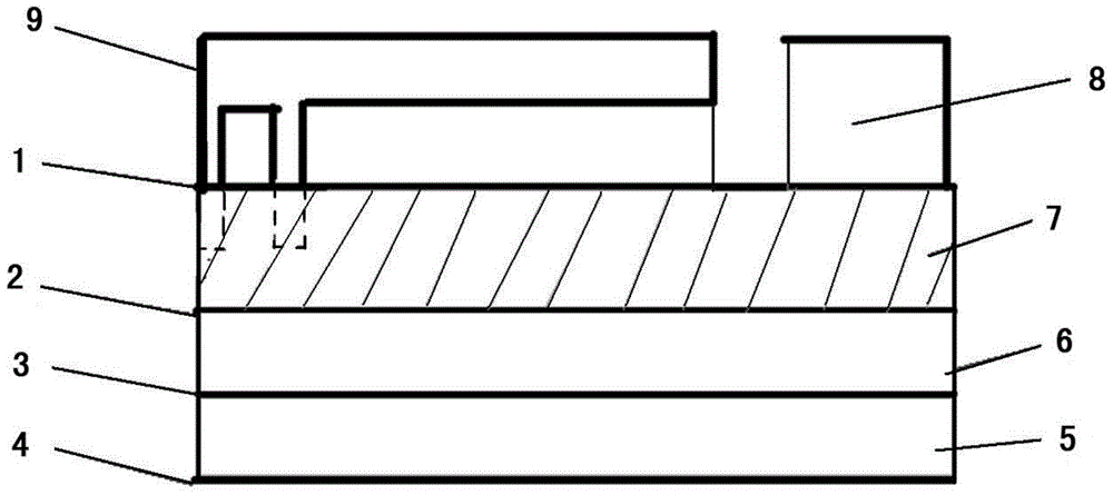
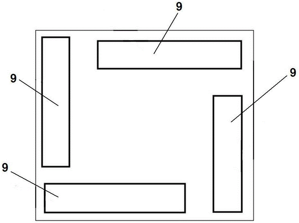
[0021] Such as figure 1 with figure 2 As shown, a small circularly polarized antenna provided by an embodiment of the present invention includes a feeder board and four radiation elements 9 mounted on one side of the feeder board. There is a feed network on the feed board, and the feed network has four output terminals, and the four output terminals are respectively connected to the four radiation elements 9 . The feed network is used to process the input signal into four signals with equal power and 90° phase difference, and output them to the four radiation elements 9 respectively.

[0022] The feed board in the embodiment of the present invention is a multi-layer structure, including a first insulating dielectric board 5, a second insulating dielectric board 6, a third insulating dielectric board 7 and a four-...


PUM


Abstract

The invention relates to a small circularly-polarized antenna comprising a feeding plate and four radiation oscillators mounted on one side face of the feeding plate. The feeding plate is provided with a feeding network, and the feeding network has four output ends which are respectively connected with the four radiation oscillators and used for generating four equal-power signals, of which the phase difference is 90 degrees, and respectively outputting the four signals to the four radiation oscillators. The radiation oscillators are PIFA oscillators, and low-loss insulating medium or gas of which the dielectric constant is greater than 2 is filled between horizontal portions of the radiation oscillators and the surface of the feeding plate. According to the small circularly-polarized antenna provided by the embodiment of the invention, by filling high-dielectric-constant low-loss insulating medium between the PIFA radiation oscillators and the feeding plate, the size of the antenna is greatly reduced, circular polarization is realized, and meanwhile, the cost of production is lowered. Compared with the prior art, the small circularly-polarized antenna of the invention has the advantages of small size, low profile, good circular polarization performance, high gain and the like.

Description

technical field [0001] The invention relates to the field of RFID application technology, in particular to a small circularly polarized antenna. Background technique [0002] Radio frequency identification is a non-contact automatic identification technology. In the RFID (Radio Frequency Identification, radio frequency identification) system, identification information is stored in an electronic data carrier, and the electronic data carrier becomes a transponder. The identification information stored in the transponder is read by the reader. In some applications, the reader can not only read the stored information, but also write data to the transponder. This read and write operation is through wireless communication between the two parties. to achieve. Microstrip antenna, as a commonly used directional antenna form in RFID system, is of great significance to the development and application of RFID. [0003] The structure of the early development of the microstrip antenna...

Claims


Application Information

Patent Timeline
Patent Type & Authority Applications(China)
IPC IPC(8): H01Q21/24H01Q9/04
Inventor 吴壁群
Owner 深圳市博纬智能识别科技有限公司
Why Eureka
Try Eureka