Microelectromechanical sound detection apparatus and method for producing such an apparatus

A detection device and micro-electromechanical technology, applied in microelectronic microstructure devices, measurement devices, electrical devices, etc., can solve the problems of expensive manufacturing, microphone damage, etc., and achieve reduced manufacturing costs, low costs, and reduced thickness. Effect

Active Publication Date: 2014-02-26
ROBERT BOSCH GMBH
View PDF7 Cites 7 Cited by
  • Summary
  • Abstract
  • Description
  • Claims
  • Application Information

AI Technical Summary

Problems solved by technology

But this requires costly manufacturing ...

Method used


Image

  • Microelectromechanical sound detection apparatus and method for producing such an apparatus
  • Microelectromechanical sound detection apparatus and method for producing such an apparatus
  • Microelectromechanical sound detection apparatus and method for producing such an apparatus

Examples


Embodiment Construction

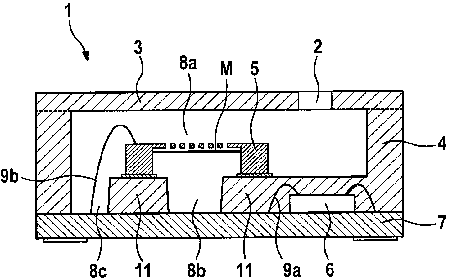
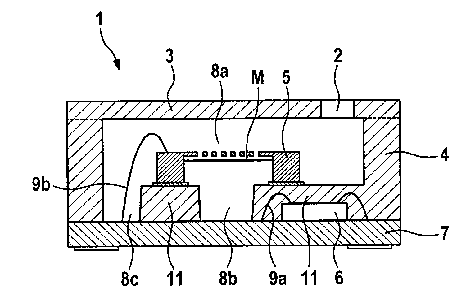
[0029] figure 1 A microelectromechanical sound detection device according to a first embodiment is shown in cross-section in schematic form.

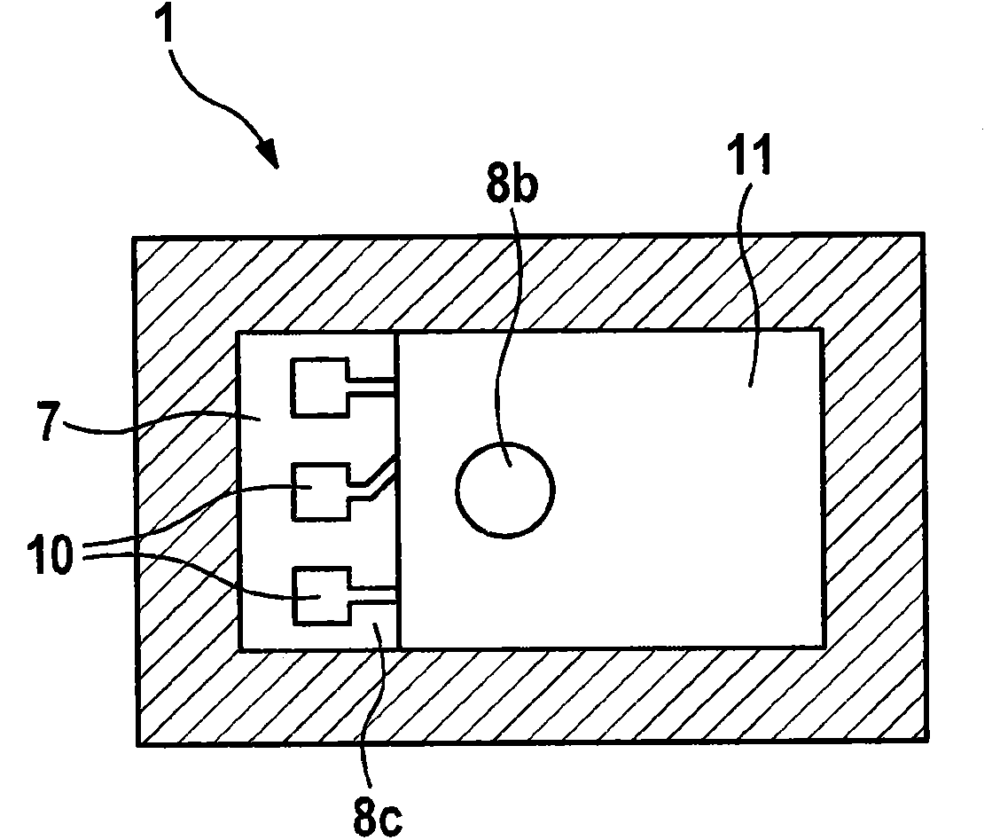
[0030] exist figure 1 In the reference numeral 1 denotes a microelectromechanical sound detection device. The MEMS sound detection device includes a land grid array circuit board 7 as a substrate. An application-specific integrated circuit 6 is arranged on the planar grid array circuit board 7, which is connected to the planar grid array circuit board 7 by wire bonds 9a for electrical contact. The application specific integrated circuit 6 is housed in a part of the wall of the moulded housing 4 . The molded housing 4 is also fixedly connected to the planar grid array circuit board 7 . The molded housing 4 is essentially hollow on the inside and has a cover 3 in the upper region of the molded housing 4 . at the envisaged vertical midline (at figure 1 On the right side from top to bottom) in the cover plate 3 is arranged an opening ...


PUM


Abstract

The invention relates to a microelectromechanical sound detection apparatus, comprising a substrate, a housing, at least one opening for sound to pass through and a microelectromechanical element for picking up sound, wherein the housing is produced by means of moulding such as to provide a front volume and a rear volume for sound detection by means of the microelectromechanical element as cavities. The invention likewise relates to a method for producing a microelectromechanical sound detection apparatus and also to uses for a sound detection apparatus.

Description

technical field [0001] The invention relates to a microelectromechanical sound detection device, a method for manufacturing the microelectromechanical sound detection device, and the application of the microelectromechanical sound detection device. Background technique [0002] Microelectromechanical sound detection devices are used, for example, in multimedia devices, mobile phones, digital cameras, bluetooth headsets or the like and in particular for picking up speech, for example during recording or during phone calls with a mobile phone. [0003] It is already known to the applicant that, for microelectromechanical elements in the form of microphones for sound detection, first the corresponding microelectromechanical elements are mounted on a substrate by means of chip-on-board (COB) technology, electrically contacted and shielded with a cover plate. In order that the sound can now be detected by means of the microphone, the sound can hit the diaphragm of the microphone ...

Claims


Application Information

Patent Timeline
IPC IPC(8): H04R19/00H04R19/04H04R31/00
CPCH04R19/04H04R19/005B81B7/0061B81C2203/0154B81B2201/0257G01H11/06H04R2499/11H04R31/00H01L2224/48091H01L2924/15151H01L2924/16151H01L2924/16195H01L2924/1815
Inventor J·策林U·肖尔茨R·埃伦普福特
Owner ROBERT BOSCH GMBH
Why Eureka
Try Eureka