High-energy photon deodorization device

A light quantum and high-energy technology, which is applied to the separation of dispersed particles, chemical instruments and methods, and separation methods, can solve problems such as insufficient ultraviolet light intensity, and achieve the effect of improving processing capacity

Active Publication Date: 2014-03-05
哈尔滨北方环保工程有限公司
View PDF6 Cites 3 Cited by
  • Summary
  • Abstract
  • Description
  • Claims
  • Application Information

AI Technical Summary

Problems solved by technology

[0003] The purpose of the present invention is to provide a high-energy light quantum deodorization device to solve the defect of insufficient UVC band ultraviolet intensity produced by UV photolysis

Method used


Image

  • High-energy photon deodorization device
  • High-energy photon deodorization device
  • High-energy photon deodorization device

Examples


specific Embodiment approach 1

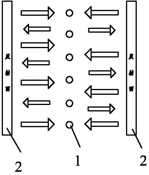
[0008] Specific implementation mode one: the following combination Figure 4 , Figure 5 This embodiment will be specifically described. This embodiment includes a cylinder body 6, an air inlet port 7 and an air outlet port 8, and the air inlet port 7 and the air outlet port 8 are respectively arranged at both ends of the cylinder body 6, and it also includes N groups of narrow-wave excitation light sources 1 and N+1 groups of light reflection plates 2, each group of narrow-wave excitation light source 1 is composed of a power conversion circuit 1-1 and a plurality of luminous tubes 1-2, and a plurality of luminous tubes 1-2 are arranged in parallel with each other In the plane, the power conversion circuit 1-1 supplies power to a plurality of light-emitting tubes 1-2; N+1 groups of light reflecting plates 2 are arranged in parallel and at equal intervals, and any two light reflecting plates of N+1 groups of light reflecting plates 2 A group of narrow-wave excitation light s...

specific Embodiment approach 2

[0012] Specific implementation mode two: the following combination Figure 4 This embodiment will be specifically described. The difference between this embodiment and Embodiment 1 is that it also includes a front-end filter 9 and a rear-end filter 10. The front-end filter 9 is arranged in the cylinder body 6 adjacent to the air inlet port 7 and separates the cylinder body. The end of the cylinder 6 is filled; the rear filter 10 is arranged in the cylinder 6 adjacent to the air outlet 8 of the exhaust end and fills the end of the cylinder 6 . Such setting increases the filter equipment and improves the purity of the treated gas.

specific Embodiment approach 3

[0013] Specific implementation mode three: the following combination Figure 4 This embodiment will be specifically described. The difference between this embodiment and the second embodiment is that each group of narrow-wave excitation light sources 1, each group of light reflection plates 2, front-end filter 9 and rear-end filter 10 are respectively installed in a drawer body, and each drawer body is viewed from the side. The side is inserted into the cylinder body 6 and fixed. With such arrangement, it is convenient to disassemble, replace and maintain. Figure 8 It is a structural schematic diagram of the third embodiment of high-energy light quantum equipment, which is composed of two 5000m 3 / h air volume high-energy photon deodorization equipment series module combination form, the series module combination form is conducive to the treatment of high-concentration malodorous gases.


PUM


Abstract

The invention relates to an air purification and deodorization device and in particular relates to a high-energy photon deodorization device. The shortcoming that a UVC (short wave ultraviolet) wave band produced by adopting a UV (ultraviolet) photolysis method is insufficient in ultraviolet intensity is overcome. The high-energy photon deodorization device comprises a barrel body, an air inlet end tuyere and an air exhaust end tuyere, wherein the air inlet end tuyere and and air exhaust end tuyere are respectively formed in two ends of the barrel body. The high-energy photon deodorization device also comprises N groups of narrow-wave excitation light sources and (N+1) groups of light reflection plates; each group of narrow-wave excitation light sources consists of a power supply conversion circuit and a plurality of light emitting tubes; the light emitting tubes are parallel to one another and are positioned in the same plane; the power supply conversion circuit supplies power to the corresponding light emitting tubes; the (N+1) groups of light reflection plates are parallel to one another and are arranged at equal intervals; each group of narrow-wave excitation light sources are arranged between every two adjacent light reflection plates of the (N+1) groups of light reflection plates; the N groups of narrow-wave excitation light sources and the (N+1) groups of light reflection plates are arranged in the barrel body; a clearance between one narrow-wave excitation light source and the corresponding light reflection plate is formed along the length direction of the barrel body.

Description

technical field [0001] The invention relates to an air purification and deodorization device, in particular to a light quantum air deodorization device. Background technique [0002] There are many air purification methods. The UV photolysis purification method uses UV ultraviolet rays to crack the molecular chains of oxidized and odorous substances in the photolysis purification equipment, change the material structure, and crack and oxidize high-molecular pollutants into low-molecular harmless substances. Theory It can handle ammonia, hydrogen sulfide, methyl mercaptan, methyl sulfide, benzene, styrene, carbon disulfide, trimethylamine, dimethyl disulfide and other high-concentration mixed gases. However, the intensity of ultraviolet light in the UVC band produced by UV photolysis is insufficient, which makes it difficult to achieve satisfactory results in industrial applications. Contents of the invention [0003] The purpose of the present invention is to provide a hi...

Claims


Application Information

Patent Timeline
IPC IPC(8): B01D53/74
Inventor 战树峰
Owner 哈尔滨北方环保工程有限公司
Why Eureka
Try Eureka