Method for improving weld penetration of optical fiber laser welding

A fiber laser and weld penetration technology, applied in laser welding equipment, welding equipment, metal processing equipment, etc., can solve problems such as laser welding weld penetration, and achieve the effect of improving weld penetration and welding efficiency.

Active Publication Date: 2014-03-05
CENT IRON & STEEL RES INST
View PDF5 Cites 4 Cited by
  • Summary
  • Abstract
  • Description
  • Claims
  • Application Information

AI Technical Summary

Problems solved by technology

Solve the problem of existi...

Method used


Image

  • Method for improving weld penetration of optical fiber laser welding
  • Method for improving weld penetration of optical fiber laser welding
  • Method for improving weld penetration of optical fiber laser welding

Examples


Embodiment 1

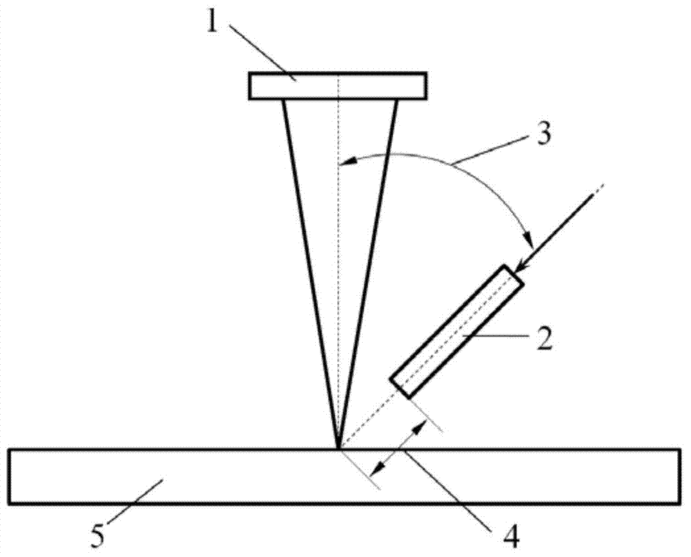
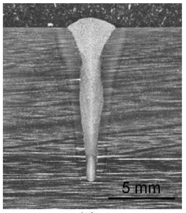
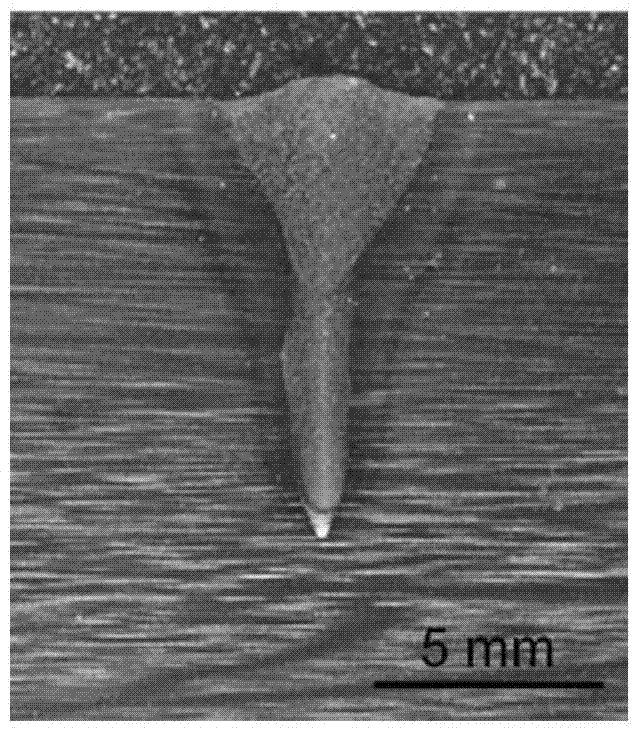
[0025] For the 20mm thick 780MPa grade high-strength steel, that is, the workpiece 5, the fiber laser welding method is adopted, wherein the laser power of the laser 1 is 7kW, the flow rate of the laser shielding gas 2 is 45L / min, and the welding speed is 1.0m / min; the shielding gas used The angle 3 between the nozzle and the laser beam is 45°, and the distance 4 between the nozzle and the workpiece is 12 mm. The original method is to use He as the shielding gas, and the shape of the laser pinhole is as follows Figure 5 As shown, the penetration depth of the weld is 9.5mm, such as image 3 shown. Now use He-20%O 2 As a shielding gas, the shape of the laser hole is as follows Figure 4 As shown, compared with He protection, the shape of the laser hole is significantly expanded, and the depth of the hole is greatly increased, so that the weld penetration depth reaches 11.5mm, as shown in figure 2 shown. It is proved that when a small amount of active gas is added to the i...

Embodiment 2

[0027] For the 20mm thick 780MPa grade high-strength steel, that is, the workpiece 5, the fiber laser welding method is adopted, wherein the laser power of the laser 1 is 7kW, the flow rate of the laser shielding gas 2 is 20L / min, and the welding speed is 1.0m / min; the shielding gas used The angle 3 between the nozzle and the laser beam is 45°, and the distance 4 between the nozzle and the workpiece is 15 mm. The original method uses Ar as the shielding gas, and the weld penetration depth is 8.7mm, such as Figure 7 shown. Ar-50%CO is now used 2 When used as a shielding gas, the weld penetration reaches 10.4mm, such as Image 6 shown. Using Ar-CO 2 Mixed gas as a shielding gas can effectively improve the weld penetration.

Embodiment 3

[0029] For the 25mm thick 490MPa grade low carbon steel, that is, the workpiece 5, the fiber laser welding method is adopted, wherein the laser power of the laser 1 is 10kW, the flow rate of the laser shielding gas 2 is 30L / min, and the welding speed is 1.0m / min; The angle 3 between the gas nozzle and the laser beam is 40°, and the distance 4 between the nozzle and the workpiece is 10 mm. When the original method uses Ar as the shielding gas, the weld penetration depth is 11.9mm. And now using Ar-20%O 2 When used as a shielding gas, the weld penetration reached 14.2mm, and the penetration increased by about 19%.


PUM


Abstract

The invention discloses a method for improving weld penetration of optical fiber laser welding. In the optical fiber laser welding process, the weld penetration is realized through changing gas composition, namely, the mixed gas of inert gas and active gas is used as protection gas. The mixed gas comprises He-O2 mixed gas, wherein the proportion of O2 is 5%-20%, Ar-O2 mixed gas, wherein the proportion of O2 is 5%-20%, He-CO2 mixed gas, wherein the proportion of CO2 is 10%-50%, and Ar-CO2 mixed gas, wherein the proportion of CO2 is 10%-50%. The method has the advantages of increasing the depth of small laser holes and improving the weld penetration through adjusting the content of active gas in the protection gas.

Description

technical field [0001] The invention belongs to the field of welding technology, in particular to a method for increasing the penetration depth of fiber laser welding seam. Background technique [0002] During laser deep penetration welding, the laser irradiance is greater than 10 6 W / cm 2 , The material is rapidly melted and vaporized under the action of a high-energy-density laser beam to form laser holes. Due to the existence of small holes, the laser beam energy can penetrate deep into the material to form a deep and narrow weld, and the weld depth-to-width ratio can reach more than 10:1. Laser deep penetration welding is a typical representative of laser welding. Compared with traditional welding methods, it has the advantages of large weld depth-to-width ratio, fast welding speed, narrow heat-affected zone, small welding deformation, high welding quality, and easy control. Therefore, laser deep penetration welding is considered to be an ideal welding method, and has...

Claims


Application Information

Patent Timeline
IPC IPC(8): B23K26/24
CPCB23K26/125B23K26/24
Inventor 赵琳田志凌张岩
Owner CENT IRON & STEEL RES INST
Why Eureka
Try Eureka