Stud welding method based on coating self-protection

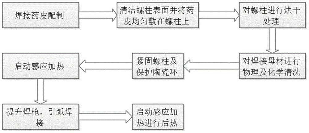
A self-protection, stud welding technology, used in welding equipment, arc welding equipment, manufacturing tools, etc., can solve the problems of uneven welding pool, arc arc burning, welding joint pores and hot cracks, etc., to achieve good welding. The effect of seam metallographic structure, reducing welding arc offset and improving weld quality

Inactive Publication Date: 2016-04-13
NANJING UNIV OF SCI & TECH
View PDF7 Cites 8 Cited by
  • Summary
  • Abstract
  • Description
  • Claims
  • Application Information

AI Technical Summary

Problems solved by technology

Now in the actual use of stud welding, the following welding problems mainly occur: 1. For large-diameter studs, there is obvious arc deviation during the arc drawing process and the arc combustion is unstable, and the studs cannot be completely burned. The end face will cause uneven melting of the stud and uneven formation of the weld pool. After the molten pool solidifies, it will seriously affect the static mechanical properties of the welded joint and cause the welded joint to fail to achieve the expected appearance (stud skew).
2. Since the plate is medium-thick medium-carbon and high-carbon steel, pores and hot cracks are likely to occur in the welded joint during the welding process. After welding, the welding stress is concentrated, which easily produces hard and brittle phases, and the welded joint produces cold cracks, which seriously affects Impact toughness and dynamic mechanical properties of welded joints
At present, there is no effective method to solve these problems in stud welding

Method used


Image

  • Stud welding method based on coating self-protection
  • Stud welding method based on coating self-protection

Examples


Embodiment 1

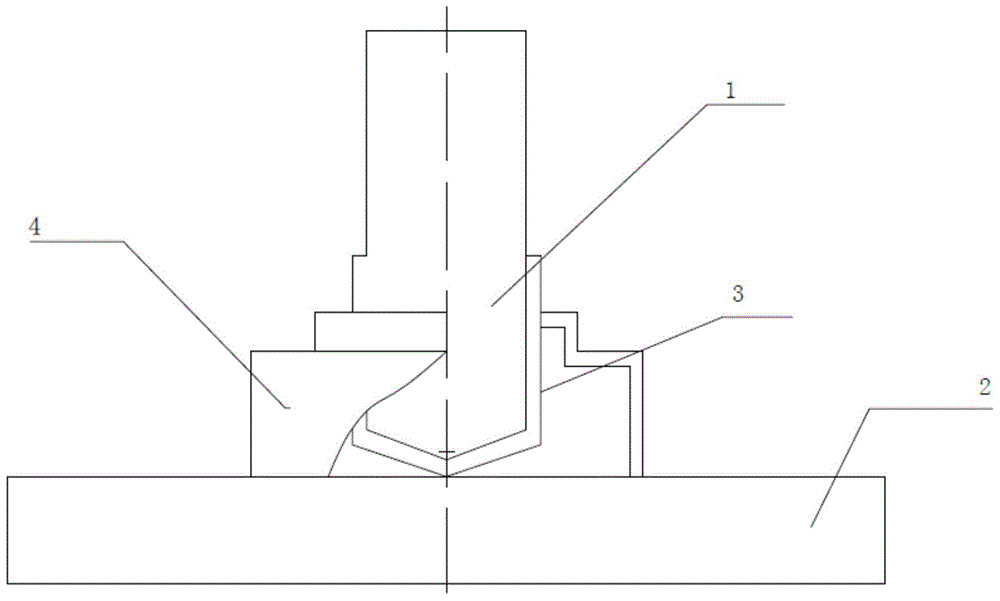
[0020] combine figure 1 and figure 2 , taking a Q235 steel stud 1 with a diameter of 8mm as an example. First prepare protective coating 3 before welding (protective coating 3 composition is; 20% CaO, 10% TiO 2 , 3% fluorite, 8% cryolite, 3% medium carbon ferromanganese powder, 10% Ni powder, 1% V powder, 2% Mo powder, 2% Cr powder, and the rest is Cr 2 o 3 pink. The bonding material is sodium silicate with a modulus of not less than 2.5 and a Baume degree of 45 degrees), and the steel stud 1 welded stud is polished to remove rust, and the steel stud 1 is treated with acetone solution. Cleaning, mixing the ingredients of the coating and the binder, the weight ratio of the binder to the coating is 15-11:100, and then adding the coating mud mixed with the binder into the ceramic mold, The shape of the mold is consistent with that of the steel stud 1, and the diameter of the mold is 10 mm; then, the cleaned steel stud 1 is slowly pressed into the mold. Fix the steel stud 1...

Embodiment 2

[0022] combine figure 1 and figure 2 , taking a Q235 steel stud 1 with a diameter of 16mm as an example. First prepare protective coating 3 before welding (protective coating 3 composition is; content 22% CaO, 13% TiO 2 , 6% fluorite, 6% cryolite, 1% medium carbon ferromanganese powder, 13% Ni powder, 0.6% V powder, 1% Mo powder, 2% Cr powder, and the rest is Cr 2 o 3 pink. The bonding material is sodium silicate with a modulus of not less than 2.5 and a Baume degree of 45 degrees), and the steel stud 1 welded stud is polished to remove rust, and the steel stud 1 is treated with acetone solution. Cleaning, mixing the ingredients of the coating and the binder, the weight ratio of the binder to the coating is 15-11:100, and then adding the coating mud mixed with the binder into the ceramic mold, The shape of the mold is consistent with that of the steel stud 1, and the diameter of the mold is 18 mm; then, the cleaned steel stud 1 is slowly pressed into the mold. Fix the s...

Embodiment 3

[0024] combine figure 1 and figure 2 , taking a Q235 steel stud 1 with a diameter of 27mm as an example. First prepare protective coating 3 before welding (protective coating 3 composition is; content 25% CaO, 15% TiO 2 , 8% fluorite, 8% cryolite, 1% medium carbon ferromanganese powder, 18% Ni powder, 0.6% V powder, 1% Mo powder, 5% Cr powder, and the rest is Cr 2 o 3 pink. The bonding material is sodium silicate with a modulus of not less than 2.5 and a Baume degree of 45 degrees), and the steel stud 1 welded stud is polished to remove rust, and the steel stud 1 is treated with acetone solution. Cleaning, mixing the ingredients of the coating and the binder, the weight ratio of the binder to the coating is 15-11:100, and then adding the coating mud mixed with the binder into the ceramic mold, The shape of the mold is consistent with that of the steel stud 1, and the diameter of the mold is 30mm; then the cleaned steel stud 1 is slowly pressed into the mold. Fix the ste...


PUM

PropertyMeasurementUnit
diameteraaaaaaaaaa
diameteraaaaaaaaaa
diameteraaaaaaaaaa

Abstract

The invention discloses a stud welding method based on coating self-protection.The stud welding method based on coating self-protection comprises following steps: preparing and welding self-protective coating composition; machining steel studs to be of 150 degrees; grinding, cleaning and removing surface stains of the steel studs and a welding region of base material; applying prepared self-protective coating material to the welding positions of the surface of the steel studs and drying self-protective coating material; horizontally placing base material, downwardly placing the tapered end of the steel studs sleeved with matching ceramic rings to be vertical to base material and applying certain pressure; and lifting the steel studs, arching and finishing welding. The stud welding method based on coating self-protection has following beneficial effects: fine welding metallographic structure is obtained and welding quality is effectively improved; operation is performed easily and efficiency is significantly increased; arc deflection is prevented and splattering during a welding process is also prevented; high-quality welding joints without defects such as oxide inclusion, lack of penetration and incomplete fusion are achieved between the steel studs and base material; welding penetration of the steel studs is improved; and the stud welding method is suitable for the steel studs of more than 8 mm in different diameters and base material of different thicknesses.

Description

technical field [0001] The invention relates to the stud welding technology for special structure of medium-carbon quenched and tempered steel, especially aimed at arc instability, shallow penetration and welding defects during common stud welding. Background technique [0002] Arc stud welding is a welding method for welding stud or columnar metal to the surface of a metal sheet. Its essence is a welding method with the same principle as fusion welding. As a fusion welding method, compared with the traditional stud processing, stud welding has the characteristics of saving time and materials, and because stud welding does not need to open holes on the surface of the plate, for some equipment that requires relatively high sealing performance Among them, stud welding can effectively avoid leakage accidents. Due to the above characteristics of stud welding, stud welding has great development prospects in the heavy machining industry and large pressure vessels. [0003] For ...

Claims


Application Information

Patent Timeline
Patent Type & Authority Applications(China)
IPC IPC(8): B23K9/20B23K9/235
Inventor 张德库薛守立王克鸿王建严泽钢
Owner NANJING UNIV OF SCI & TECH
Why Eureka
Try Eureka