Steel box beam orthotropic deck slab

A technology for orthotropic bridges and steel box girders, applied in bridges, bridge parts, bridge construction, etc., can solve problems such as fatigue cracks, achieve the effects of eliminating welding fatigue cracks, avoiding excessive local deformation, and prolonging service life

Active Publication Date: 2014-03-05
SOUTHEAST UNIV
View PDF6 Cites 16 Cited by
  • Summary
  • Abstract
  • Description
  • Claims
  • Application Information

AI Technical Summary

Problems solved by technology

[0006]Technical problem: The present invention provides a method that can significantly improve the transverse bending stiffness of the bridge deck, thereby reducing the possibility of longitudinal cracking of the pavement, a...

Method used


Image

  • Steel box beam orthotropic deck slab
  • Steel box beam orthotropic deck slab
  • Steel box beam orthotropic deck slab

Examples


Embodiment Construction

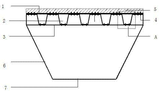
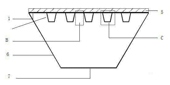
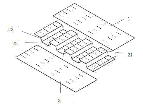
[0026] see figure 1 , the orthotropic steel bridge deck includes an upper roof 1, a corrugated steel plate 2 and a lower roof 3, the wave direction of the corrugated steel plate 2 is consistent with the direction of the transverse bridge, and the corrugated steel plate 2 is composed of crest surfaces 21 and trough surfaces staggered along the direction of the transverse bridge 22. It consists of a slope 23 connecting the crest surface 21 and the trough surface 22. The included angle between the inclined surface 23 and the crest surface (21) and the included angle between the inclined surface 23 and the trough surface 22 are not 90°, and the wave section of the corrugated steel plate 2 is a plurality of continuously arranged trapezoids. The upper top plate 1, the lower top plate 3 and the corrugated steel plate 2 are connected by high-strength bolts 4 . The high-strength bolts 4 expose about 3-5 centimeters on the upper side of the upper roof 1, as the shear bond between the ...


PUM


Abstract

The invention discloses a steel box beam orthotropic deck slab. The steel box beam orthotropic deck slab comprises an upper top plate, a corrugated steel plate and a lower top plate which are sequentially connected from top to bottom. The corrugated direction of the corrugated steel plate is consistent with the transverse bridge direction. The corrugated steel plate is composed of crest surfaces, trough surfaces and inclined planes connected with the crest surfaces and the trough surfaces, wherein the crest surfaces, the trough surfaces and the inclined planes are staggered in the transverse bridge direction. Included angles of the inclined planes and the crest surfaces and included angles of the inclined planes and the trough surfaces are not 90 degrees, and the corrugated cross section of the corrugated steel plate is a plurality of continuously arranged trapezoids. The corrugated steel plate is utilized to serve as a longitudinal stiffening rib of a steel box beam deck top plate, the orthotropic slab formed by the upper top plate, the lower top plate and the middle layer corrugated steel plate is similar to a parallel chord truss with an inclined web member in the transverse bridge direction, pressure resistance stability and transverse flexural rigidity of the deck slab are improved, and excessive local deformation under the effect of a concentrated wheel load is effectively avoided. According to the steel box beam orthotropic deck slab, a traditional welding mode is abandoned, bolting is adopted completely, and the problem of fatigue cracking of welding cracks can be solved thoroughly.

Description

technical field [0001] The invention belongs to the technical field of bridge structures and relates to an orthotropic deck structure suitable for steel box girder bridges. Background technique [0002] At present, the long-span suspension bridges and cable-stayed bridges of highways basically use streamlined steel box girders as stiffening girders. However, due to the greater structural flexibility of the steel box girder, the steel bridge deck generally adopts an orthotropic plate structure, that is, the longitudinal U-shaped ribs, transverse ribs, and diaphragms are used to strengthen the steel bridge deck to increase its rigidity. But even so, the cracking problem of the steel bridge deck pavement is still not well resolved. The current steel bridge deck pavement mainly has the following three problems. [0003] The first is the cracking of the longitudinal bridge to the deck pavement. This kind of typical cracking is due to the fact that the orthotropic steel deck is...

Claims


Application Information

Patent Timeline
IPC IPC(8): E01D19/12
Inventor 吴文清刘玉龙余江昱
Owner SOUTHEAST UNIV
Why Eureka
Try Eureka