Tension-compression and torsion vibration fatigue test device

A fatigue test and torsional vibration technology, applied in the direction of applying repetitive force/pulsation force to test the strength of materials, can solve the problems of time-consuming, labor-intensive, and long-time consumption, and achieve the effects of improving test efficiency, reducing operating temperature, and reducing heat

Active Publication Date: 2014-03-05
北京乐冶液压气动设备技术有限公司 +1
View PDF7 Cites 19 Cited by
  • Summary
  • Abstract
  • Description
  • Claims
  • Application Information

AI Technical Summary

Problems solved by technology

Because it takes a long time to conduct a fatigue test, the

Method used


Image

  • Tension-compression and torsion vibration fatigue test device
  • Tension-compression and torsion vibration fatigue test device
  • Tension-compression and torsion vibration fatigue test device

Examples


Embodiment 1

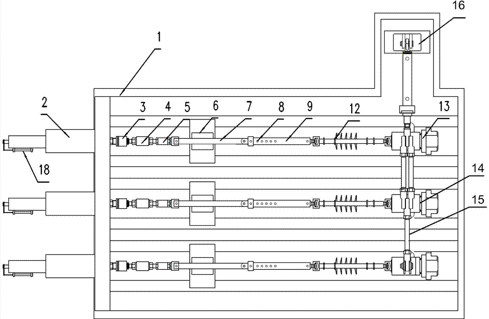
[0025] figure 1 It is a structural schematic diagram of the tension-compression and torsional fatigue vibration test device of this embodiment, which includes a test device bench 1, 3 sets of tension-compression test mechanisms and 1 set of torsion test mechanisms. This embodiment only takes 3 stations as an example. In practice, more workstations can be designed according to needs and space. In this embodiment, the tension-compression and torsional fatigue vibration tests of three tested workpieces can be completed simultaneously.

[0026] Such as figure 1 As shown, each tension-compression test mechanism includes a tension-compression cylinder 2 , a first connector 3 , a force sensor 4 , a second connector 5 , a guide mechanism 6 , a guide rod 7 and an adjustment rod 9 .

[0027] Wherein, the tension-compression actuator 2 is a linear motion conversion mechanism, which is installed on the test bench 1, and the piston rod of the tension-compression actuator 2 is connected t...

Embodiment 2

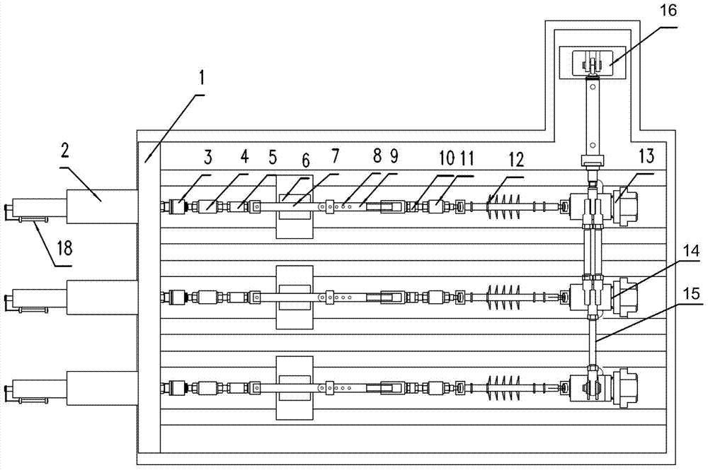
[0035] Such as image 3 As shown, this embodiment is an improvement on Embodiment 1. In this embodiment, in order to monitor the torsional moment generated under the applied torsion angle, a third connecting piece 10 and a torque sensor 11 are added, the adjusting rod 9 is connected with the torque sensor 11 through the third connecting piece 10, and the torque sensor 11 is then It is connected to one end of the workpiece 12 under test.

[0036] In addition, this embodiment also improves the adjusting rod 9 . Such as image 3 As shown, a row of equally spaced positioning holes 8 is designed at one end of the adjusting rod 9 , and the other end is connected to the screw hole provided by the third connecting piece 10 through threads. The adjusting rod 9 can be connected with the guide rod 7 through any positioning hole 8, and the space occupied by the tested workpiece 12 can be fine-tuned by adjusting the thread connection depth of the third connecting piece 10 and the adjust...

Embodiment 3

[0038] In the tension-compression fatigue test, a constant static force is usually applied to the workpiece to be tested, and then an alternating force is superimposed on this basis. In the prior art, the pulling and pressing actuator 2 usually uses a hydraulic actuator to carry out the above test. Because the test time required for the fatigue test is long, the energy consumed is very large, and the actuator will be exhausted when it works for a long time. A lot of heat is generated, causing seal damage and piston rod wear.

[0039] Therefore, the pulling and pressing actuator 2 of the present embodiment adopts a composite actuator. The composite actuating cylinder is a structure in which the static loading cylinder and the dynamic loading cylinder are integrated, as shown in FIG. 4(a), which includes a coaxially connected static loading cylinder 2-1 and a dynamic loading cylinder 2-2. The inner chambers of the static loading cylinder 2-1 and the dynamic loading cylinder 2-2...


PUM


Abstract

The invention discloses a tension-compression and torsion vibration fatigue test device capable of simultaneously accomplishing tension-compression and torsion fatigue tests. The test device comprises a test device rack, a torsion test mechanism and a plurality of tension-compression test mechanisms. In each tension-compression test mechanism, a tension-compression actuating cylinder piston rod, a force sensor, a guide rod, an adjusting rod and a tested workpiece are sequentially connected end to end, wherein the adjusting rod is provided with a plurality of adjusting positions; according to the size of the tested workpiece, the guide rod is connected to the corresponding adjusting position of the adjusting rod; the guide rod does rectilinear movement under the limitation of a guide mechanism. In the torsion test mechanism, a rotating end of each bearing slewing mechanism is connected with the other end of the tested workpiece; oscillating rods of all the bearing slewing mechanisms are connected in series by a link mechanism, and the oscillating rod at one end is connected with the piston rod of a torsion actuating cylinder through a link mechanism. Tension-compression actuating cylinders, the bearing slewing mechanisms and the torsion actuating cylinder are all fixed on the test device rack.

Description

technical field [0001] The invention relates to the technical field of vibration fatigue testing of materials, in particular to a device for testing tension, compression and torsional vibration fatigue testing of a material to be tested by using a compound actuating cylinder. Background technique [0002] When the fatigue test is carried out on the tested workpiece, it is often required to carry out both tension and compression vibration fatigue test and torsional vibration fatigue test on the tested workpiece. In the prior art, the two types of fatigue tests are performed separately, and only one type of fatigue test is completed each time. Since it takes a long time to perform a fatigue test, the existing test methods are time-consuming and labor-intensive. Aiming at this, the present invention designs a test device that can simultaneously complete tension-compression and torsion fatigue tests. Contents of the invention [0003] In view of this, the present invention p...

Claims


Application Information

Patent Timeline
IPC IPC(8): G01N3/32
Inventor 孙宝川李庆峰王军政汪首坤赵江波陈贞发陈颖高海峰殷禹魏杰
Owner 北京乐冶液压气动设备技术有限公司
Why Eureka
Try Eureka