Zero-cross detection circuit and detection method used for synchronous buck converter

A zero-crossing detection circuit and synchronous step-down technology, applied in the direction of converting DC power input to DC power output, instruments, electrical components, etc., can solve the problems of increasing circuit power consumption, error, and large fluctuation range of the zero-crossing point of the inductor current. Achieve the effect of realizing automatic correction and reducing circuit power consumption

Active Publication Date: 2014-03-05
SILERGY SEMICON TECH (HANGZHOU) CO LTD
View PDF10 Cites 36 Cited by
  • Summary
  • Abstract
  • Description
  • Claims
  • Application Information

AI Technical Summary

Problems solved by technology

[0005] But due to the zero-crossing comparator offset voltage V OS The existence of ', in high-power applications, the resistance of the synchronous tube is very small (such as: 2mΩ), the offset voltage (such as: ±10mv) will cause a large error, and the fluctuation range of the zero-crossing point of the inductor current is large. When there is no load, the zero-crossing comparator cannot be triggered, and the zero-crossing point cannot be detected, making the circuit work in forced continuous conduction mode (Force CCM), which increases the power consumption of the circuit

Method used


Image

  • Zero-cross detection circuit and detection method used for synchronous buck converter
  • Zero-cross detection circuit and detection method used for synchronous buck converter
  • Zero-cross detection circuit and detection method used for synchronous buck converter

Examples


Embodiment 1

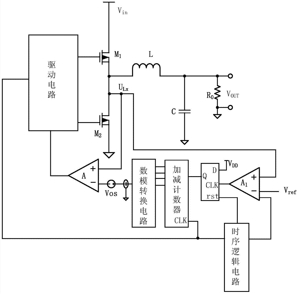
[0043] Such as figure 2 shown, using the first comparator A 1As a state judging circuit, the state judging refers to judging the synchronous tube M 2 Whether the body diode in is turned on; after the zero-crossing comparator is triggered, the synchronous tube M is turned off through the drive circuit 2 , then the first comparator A 1 Detect the drain voltage U of the synchronous tube within a sampling time Lx , compare the voltage with the reference voltage;

[0044] Since when the sync tube M 2 When the body diode is turned on, its voltage drop is 0.7v. You can set the value of the reference voltage to -0.3~-0.5v or +0.3~0.5v for comparison. The inductor current is positive from left to right. When When the body diode conducts, U Lx The voltage at the point is roughly -0.7v, U Lx The voltage at the point is connected to the non-inverting input terminal of the first comparator, and the reference voltage value -0.4v is connected to the first comparator A 1 The invertin...

Embodiment 2

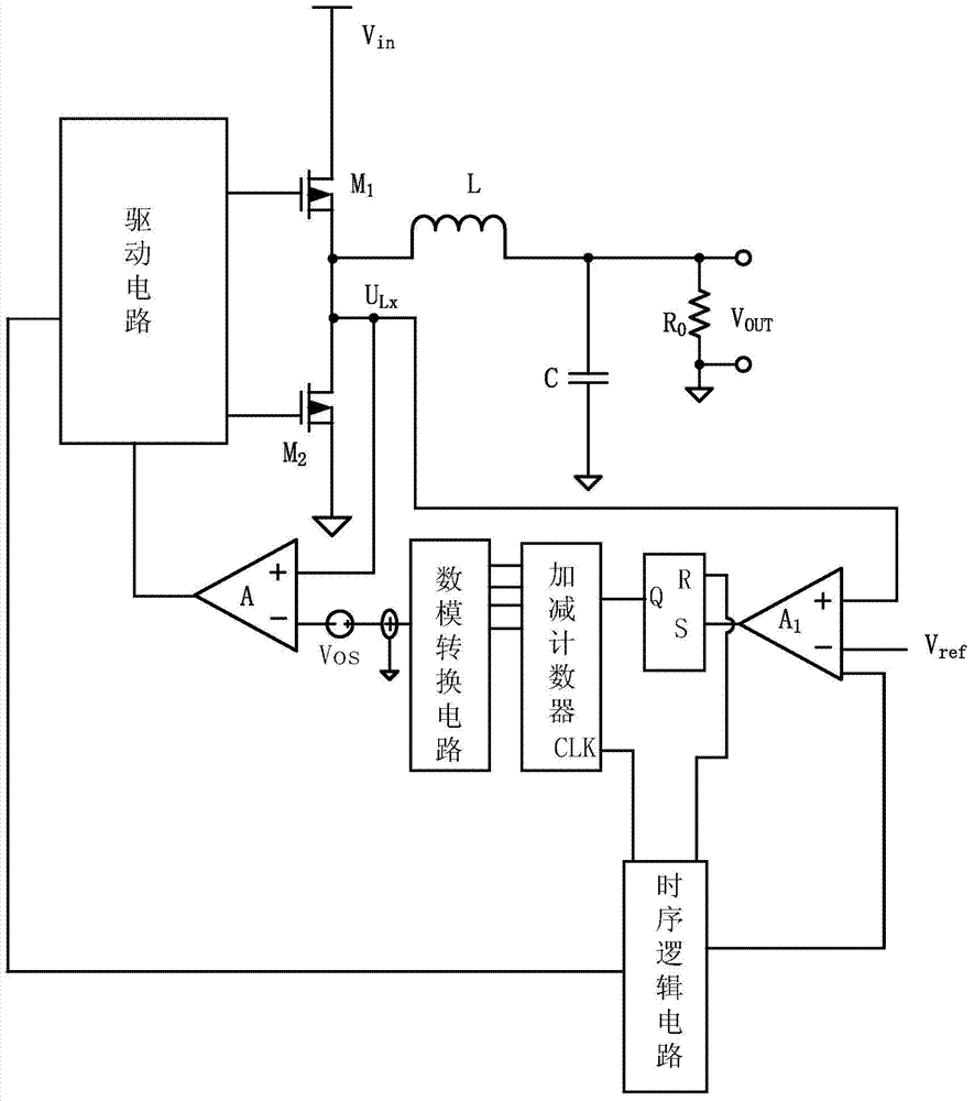
[0050] Such as image 3 As shown, the difference between embodiment 2 and 1 mainly lies in several parts such as logic circuit, sequential logic circuit and sequential signal. The logic circuit of embodiment 2 adopts an RS flip-flop, the state digital signal is connected to the S terminal of the RS flip-flop, the third timing signal is connected to the R terminal of the RS flip-flop, and the output terminal outputs counting instructions to the up-down counter.

[0051] The first timing signal is connected to the timing logic circuit, and outputs a second timing signal, a third timing signal and a fourth timing signal respectively representing the working timing of the first comparator, the logic circuit and the up-down counter. The second timing signal is a high level set for a certain sampling time on the rising edge of the first timing signal, and the third timing signal is a low level set for a certain period of time on the rising edge of the first timing signal. The fourt...


PUM


Abstract

The invention discloses a zero-cross detection circuit and detection method used for a synchronous buck converter. The zero-cross detection circuit comprises a state judging circuit, a logic circuit, an adding and subtracting counting circuit, a digital-to-anology converting circuit and a zero-crossing comparator; the direction of a current passing through an inductor can be judged according to the state of a body diode of a lock-in tube, if the body diode is powered on, it is illustrated that a threshold value of zero-cross detection is positive, the threshold value can be decreased in the next period, it is illustrated that the threshold value of zero-cross detection is negative until the diode is cut off, and the threshold value can be increased in the next period. Output of the digital-to-anology converting circuit is regulated through the adding and subtracting counting circuit to decrease and increase the threshold value, signals are optimized through a balance module to form correction analog signals, and therefore positive and negative correction within a certain range is achieved, dynamic balance of zero-cross detection at a zero point is achieved, automatic correction of an offset voltage of the zero-crossing comparator is achieved, and circuit power consumption is reduced.

Description

technical field [0001] The invention relates to the field of step-down converters, in particular to a zero-crossing detection circuit and a detection method for synchronous step-down converters. Background technique [0002] In the synchronous buck converter, the main switch is turned on at the beginning of each cycle, the inductor current rises, the electric energy input at the input terminal is converted into magnetic energy and stored in the magnetic field of the inductor, and the main switch is turned off when a certain duty cycle is reached. , the inductor current gradually decreases through the continuous flow of the synchronous tube, and the magnetic energy is converted into electrical energy and released to the output terminal to complete a cycle conversion. When the load is large, the inductor current will not return to zero during the entire cycle, so that the circuit is usually in the connection conduction mode (CCM); when the load is light, the inductor current g...

Claims


Application Information

Patent Timeline
Patent Type & Authority Applications(China)
IPC IPC(8): G01R19/175
CPCH02M3/1588H03K5/1536Y02B70/10H02M3/158
Inventor 侯晋昭陈琛
Owner SILERGY SEMICON TECH (HANGZHOU) CO LTD
Why Eureka
Try Eureka