Superconducting magnetic compensation device and method based on predistortion

A superconducting magnetic and magnetic compensation technology, applied in the field of magnetic compensation, can solve the problems that affect the wide application and promotion of superconducting magnetic sensors, limited magnetic field strength and frequency range, and unsatisfactory background noise in the compensation range, etc., to achieve small size, Improve range, achieve simple effects

Active Publication Date: 2014-03-05
SHANGHAI INST OF MICROSYSTEM & INFORMATION TECH CHINESE ACAD OF SCI
View PDF6 Cites 27 Cited by
  • Summary
  • Abstract
  • Description
  • Claims
  • Application Information

AI Technical Summary

Problems solved by technology

Although this method can suppress the influence of environmental field disturbance on SQUID magnetic measurement without affecting the measurement of weak signals, its stability is difficult to control because of the use of a second-order negative feedback circuit, and is affected by the SQUID's Feedback coil (feedback coil) The influence of the feedback coefficient, the magnetic field strength and frequency range that can be compensated are limited
[0006] In summary, when the existing magnetic compensation methods work in sports and field environments, either there are applicability and reliability problems, or the compensation range or background noise is not ideal, which greatly affects the application of superconducting magnetic sensors in industry and scientific research. Wide application and promotion in the medical field

Method used


Image

  • Superconducting magnetic compensation device and method based on predistortion
  • Superconducting magnetic compensation device and method based on predistortion

Examples


Embodiment Construction

[0024] In order to make the purpose, specific solutions and advantages of the present invention clearer, the present invention will be further described in detail below in conjunction with specific embodiments and with reference to the accompanying drawings.

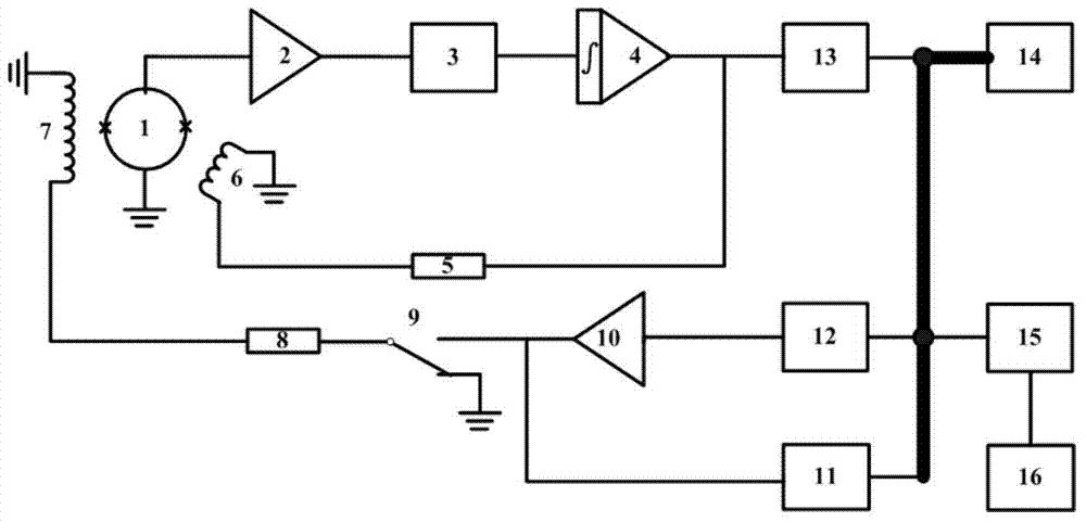
[0025] The SBC superconducting magnetic sensor 1 readout circuit based on the magnetic flux locked loop is used to complete the measurement of the magnetic signal to be measured, such as figure 1As shown, its main structure is as follows: the SBC superconducting magnetic sensor 1 placed in Dewar liquid helium is connected to the front-end amplifier 2 through a low-temperature cable, and the SBC superconducting magnetic sensor 1 has two working modes: current bias and voltage Bias, the present invention adopts the voltage bias mode, and the front-end amplifier 2 selects the inverse amplifier with a gain of 80-100dB, the model is the AD797 low-noise operational amplifier of ADI Company, and its output will be affected by th...


PUM


Abstract

The invention relates to a superconducting magnetic compensation device and method based on predistortion. The superconducting magnetic compensation device based on predistortion is characterized in that the device is composed of a reference magnetic sensor, a magnetic compensation circuit and a compensation coil, the reference magnetic sensor is used for measuring magnetic field signals of an area to be compensated, the magnetic compensation circuit is used for extracting signals of a frequency band to be compensated from the magnetic field signals measured by the reference magnetic sensor, and then the magnetic field of the specific area is compensated through the compensation coil. The compensation method is characterized in that denoising or threshold value judging digital signal processing is conducted in a controller after the measurement value of the external reference magnetic sensor is obtained through an analog-digital converter firstly, then predistortion is conducted selectively on an input signal of an SQUID device by means of a coil, with a feedback factor dozens of times higher than that of the SQUID device, driven by a power amplifier and a feedback resistor through a digital-analog converter, and finally sampling is conducted on output signals of a magnetic flow locking ring and the power amplifier through a synchronous data acquiring device. The superconducting magnetic compensation device is simple in structure, small in size, high in stability and suitable for being used during exercise or in outdoor environments.

Description

technical field [0001] The present invention relates to a magnetic compensation device and method for a superconducting magnetic sensor, in particular to a device for realizing magnetic compensation by means of pre-distortion on the basis of a traditional Flux-Locked Loop (FLL: Flux-Locked Loop) readout circuit and methods. It belongs to the field of magnetic compensation. Background technique [0002] The superconducting magnetic sensor composed of superconducting quantum interferometer (SQUID: Superconducting QUantum Interference Device) is currently the most sensitive magnetic sensor known. It has been used in many applications in magnetically shielded rooms and static working environments. In the moving platform, the magnetic field signal introduced by factors such as external strong magnetic field changes or cutting the earth's magnetic force lines can easily cause the baseline drift or even overflow of the highly sensitive SQUID readout circuit to fail to work normall...

Claims


Application Information

Patent Timeline
Patent Type & Authority Applications(China)
IPC IPC(8): G01R33/035
Inventor 伍俊荣亮亮王会武邱隆清蒋坤孔祥燕谢晓明
Owner SHANGHAI INST OF MICROSYSTEM & INFORMATION TECH CHINESE ACAD OF SCI
Why Eureka
Try Eureka