

Visible light photocatalyst and preparation method therefor
A photocatalyst and visible light technology, applied in chemical instruments and methods, physical/chemical process catalysts, metal/metal oxide/metal hydroxide catalysts, etc., can solve problems such as energy storage function of long afterglow materials, etc. Achieve the effects of low cost, simple preparation method and high organic matter removal rate
- Summary
- Abstract
- Description
- Claims
- Application Information
AI Technical Summary
Problems solved by technology
Method used
Image

Examples
preparation example Construction
[0035] A preparation method of visible light photocatalyst, is characterized in that, described preparation method comprises the following steps:
[0036] (1) According to the proportioning of claim 1, weighing the down conversion material and / or modified material; (2) Adding the weighed material into 10-20 ml of 0.05-0.2 mol / l salt solution, Put the solution into a 35 ml microwave tube and stir at 25-35°C for 0.5-1 hour to make the solution uniform; (3) Add Na(OH) dropwise 2Solution, so that the pH value of the solution is between 7-9, and stirred at room temperature 25-35 ° C for 0.5-1 hour; (4) Put the stirred solution into a microwave reaction synthesizer, at a temperature of 110-160 ° C and power Under the condition of 80-150 W, the composite photocatalyst is obtained after reacting for 10-30 minutes.
Embodiment 1
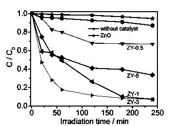
[0038] Use Y 3 Al 5 o 12 : Ce 3+ Composite visible light catalyst with ZnO.
[0039] 1) Preparation of photocatalyst
[0040] Weigh the down conversion material Y with a mass ratio of 0.5%, 1%, 3% and 5% to the semiconductor material, respectively 3 Al 5 o 12 : Ce 3+ , the weighed Y 3 Al 5 o 12 : Ce 3 were added to 20 ml of 0.1 mol / l ZnSO 4 solution, put the solution into a 35 ml microwave tube, and stir at room temperature for half an hour to make the solution uniform. Then add Na(OH) dropwise 2 solution, so that the pH of the solution = 9, stirred at room temperature for 1 hour, and then placed in a microwave reaction synthesizer, at a temperature of 150 o Under the conditions of C and power 100 W, four kinds of ZnO-Y were obtained after 10 minutes of reaction 3 Al 5 o 12 : Ce 3+ composite photocatalyst. Will Y 3 Al 5 o 12 : Ce 3+ The composite photocatalysts whose mass ratio with ZnO is 0.5%, 1%, 3% and 5% are named as ZY-0.5, ZY-1, ZY-3 and ZY-5, res...
Embodiment 2
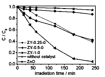
[0045] Use Y 2 o 2 S:Eu 2+ Composite visible light catalyst with ZnO.
[0046] 1) Preparation of photocatalyst
[0047] Weigh the down-conversion material Y with a mass ratio of 0.25%, 0.5% and 1% to the semiconductor material, respectively 2 o 2 S:Eu 2+ , the weighed Y 2 o 2 S:Eu 2+ were added to 20 ml of 0.1 mol / l ZnSO 4 solution, put the solution into a 35 ml microwave tube, and stir at room temperature for half an hour to make the solution uniform. Then add Na(OH) dropwise 2 solution, so that the pH of the solution = 9, stirred at room temperature for 1 hour, and then placed in a microwave reaction synthesizer, at a temperature of 150 o Under the conditions of C and power 100 W, ZnO-Y was obtained after 10 minutes of reaction 2 o 2 S:Eu 2+ composite photocatalyst. Will Y 2 o 2 S:Eu 2+ The composite photocatalysts whose mass ratio with ZnO is 0.25%, 0.5% and 1% are named as ZY-0.25-0, ZY-0.5-0 and ZY-1-0, respectively.
[0048] 2) Photocatalysis experime...
PUM
 Abstract
Description
Claims
Application Information