
Powdery material feeding system and method

A powdery material and feeding system technology, applied in loading/unloading, containers, packaging, etc., can solve the problems of feeding screw stuck, unsmooth feeding, and blocking of feeding port, etc., to reduce equipment failure rate, Guarantee continuity and stability, and prevent the effect of screw stuck

Inactive Publication Date: 2014-03-12
PANGANG GROUP RESEARCH INSTITUTE CO LTD
View PDF4 Cites 18 Cited by
  • Summary
  • Abstract
  • Description
  • Claims
  • Application Information

AI Technical Summary

Problems solved by technology

[0002] When the molten salt chlorination furnace is used to produce titanium tetrachloride, the solid powder mixture is fed from the furnace top silo. Due to the moisture in the material and the flue gas generated in the molten salt chlorination furnace during the production process, it often diffuses to the furnace top material. In the silo, the mixture of titanium slag, petroleum coke, and sodium chloride in the furnace top silo often leads to blockage of the discharge port and hardening of the furnace material, which in turn leads to the jamming of the feeding screw, increased screw wear, and serious material accumulation in the silo
At present, it is still mainly used to manually beat the hopper or disassemble and replace the stuck screw to solve the problem of unsmooth feeding, and when replacing the feeding screw, two to three people need to cooperate to manually pull out the stuck screw, and use steel brazing to manually clean the screw installation Holes, not only labor-intensive but also low in efficiency, seriously reducing the production capacity and production rate of molten salt chlorination furnace

Method used


Image

  • Powdery material feeding system and method

Examples


Embodiment Construction

[0019] Hereinafter, the feeding system and method for powdery materials according to the present invention will be described in detail with reference to the accompanying drawings and exemplary embodiments.

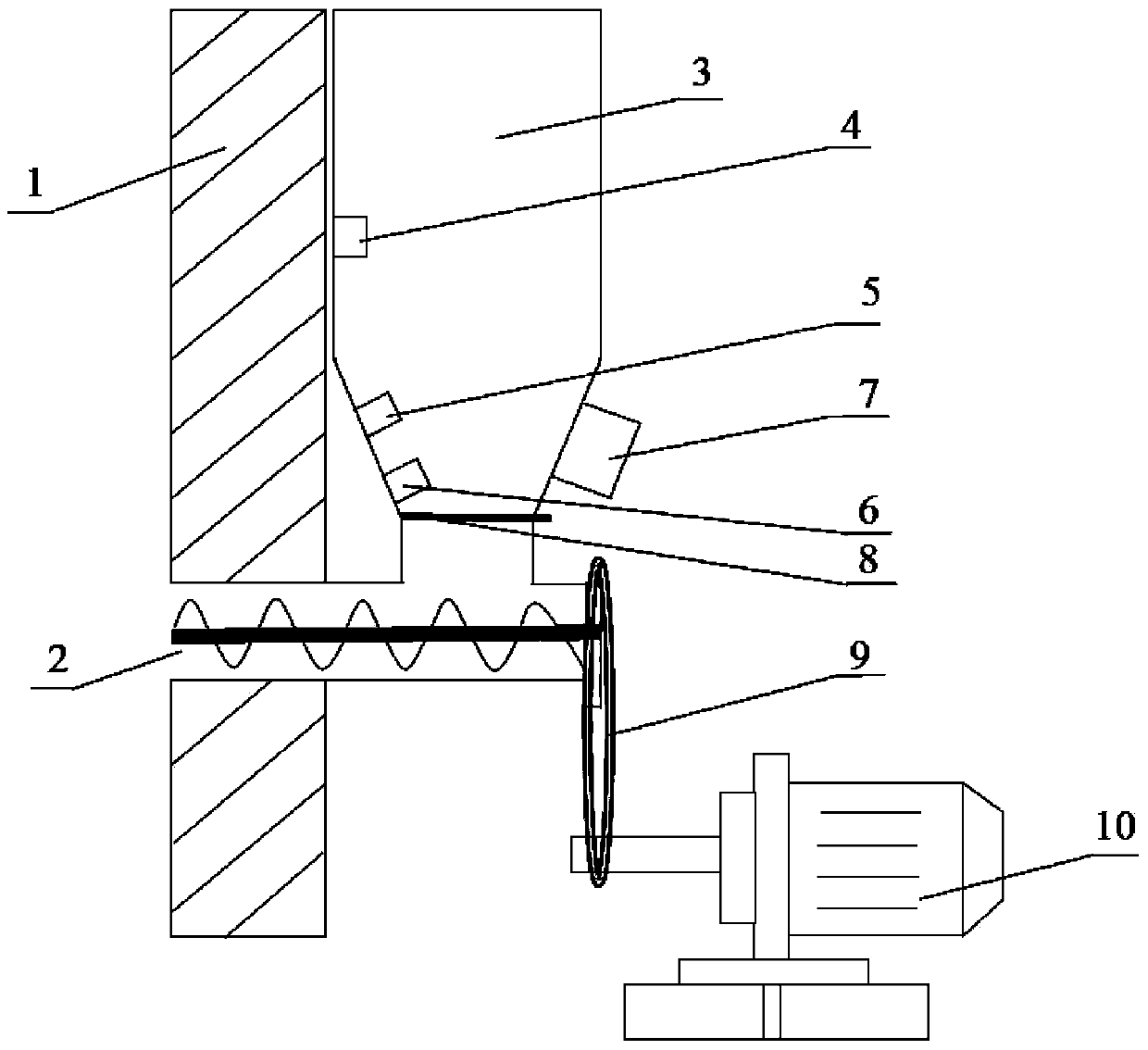
[0020] figure 1 It is a schematic structural diagram of a feeding system for powdery materials in an exemplary embodiment of the present invention. Such as figure 1 Shown, according to the feeding system of the powdery material of exemplary embodiment of the present invention, be used for solid powdery material (for example, molten salt such as titanium slag, petroleum coke and sodium chloride chlorination produces the raw material of titanium tetrachloride ) to the molten salt chlorination furnace. The feeding system includes a screw feeder 2, a silo 3, a material level detection unit (including the first material level gauge 4, the second material level gauge 5 and the third material level gauge 6), a vibrator 7, a valve 8, Drive unit (including chain 9 and variable f...


PUM


Abstract

The invention provides a powdery material feeding system and method. The feeding system is used for transmitting a powdery material to a reaction device and comprises a material bin, a raw material supply unit, a material level detection unit, a spiral feeding device, a drive unit and a vibrator. The raw material supply unit is connected with a feed port of the material bin. The spiral feeding device is connected with a discharge port of the material bin and the reaction device, and the powdery material is pushed to the reaction device in a spiral mode through the spiral feeding device after entering the spiral feeding device from a discharge port of the material bin. The drive unit is connected with the spiral feeding device and used for driving the spiral feeding device to feed the material into the reaction device and adjusting the amount of the fed material. The material level detection unit is arranged in the material bin, the material level in the material bin can be detected through the material level detection unit, the amount of the material which is supplied to the material bin through the material supply unit and the amount of the material which is fed into the reaction device through the spiral feeding device are adjusted, and therefore the material level in the material bin can be stabilized at a first position which is located between the material level upper limit of the material bin and the material level lower limit of the material bin.

Description

technical field [0001] The invention relates to a matching equipment of a molten salt chlorination furnace, more specifically, to a feeding system for the roof of a molten salt chlorination furnace for producing titanium tetrachloride. Background technique [0002] When the molten salt chlorination furnace is used to produce titanium tetrachloride, the solid powder mixture is fed from the furnace top silo. Due to the moisture in the material and the flue gas generated in the molten salt chlorination furnace during the production process, it often diffuses to the furnace top material. In the silo, the titanium slag, petroleum coke, and sodium chloride mixture in the furnace top silo often lead to blockage of the feeding port and hardening of the furnace material, which in turn leads to the jamming of the feeding screw, increased screw wear, and serious material accumulation in the silo. At present, it is still mainly used to manually beat the hopper or disassemble and replace...

Claims


Application Information

Patent Timeline
IPC IPC(8): B65G65/46B65D88/66B65D90/48
Inventor 李亮李开华程晓哲苗庆东何安西杨仰军
Owner PANGANG GROUP RESEARCH INSTITUTE CO LTD
Learn More