Phase change heat pump system

A heat pump system and phase change technology, applied in lighting and heating equipment, compressors with reversible circulation, fluid circulation arrangements, etc., can solve problems such as large energy consumption, and achieve the effect of less energy consumption and stable operation

Active Publication Date: 2014-03-12
BEIJING FULLLINK OREITH TECH CO LTD
View PDF6 Cites 10 Cited by
  • Summary
  • Abstract
  • Description
  • Claims
  • Application Information

AI Technical Summary

Problems solved by technology

[0003] The purpose of the present invention is to overcome the shortcomings of the prior art, to solve the problem of large energy consumption in the refrigeration system, and to provide a phase change heat pump system with simple structure, easy implementation, energy saving and emission reduction, so that evaporation and condensation can be realized Isothermal Phase Change Evaporation and Isothermal Phase Change Condensation

Method used


Image

  • Phase change heat pump system
  • Phase change heat pump system
  • Phase change heat pump system

Examples


Embodiment 1

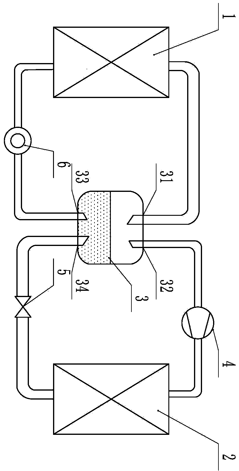
[0021] This embodiment is the workflow of the first energy transport, such as figure 1 A working flow chart of a phase change heat pump system is shown, the whole system includes an indoor heat exchanger (1), an outdoor heat exchanger (2), a liquid storage tank (3), a liquid storage tank interface 1 (31), Liquid storage tank port two (32), liquid storage tank port three (33), liquid storage tank port four (34), compressor (4), throttling device (5), circulation pump (6), connection Pipeline and circuit control part; the indoor heat exchanger (1), liquid storage tank (3), circulation pump (6) and connecting pipes form an indoor circulation loop; the outdoor heat exchanger (2), throttling device (5), liquid storage tank (3), compressor (4) and connecting pipes form an outdoor circulation loop; when the phase change heat pump system is working, the circulation pump (6) transfers the liquid working medium from the interface three ( 33) Suction is sent to the indoor heat exchanger...

Embodiment 2

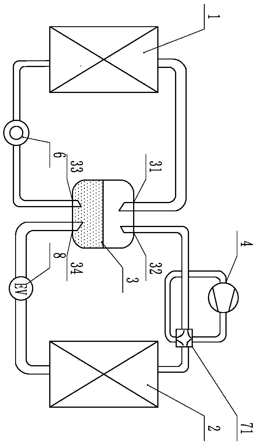
[0023] attached figure 2 It is a schematic diagram of the structure of the second embodiment of the present invention, so that the functions of the indoor heat exchanger (1) and the outdoor heat exchanger (2) in the system are exchanged, that is, the outdoor heat exchanger (2) acts as an evaporator function, the indoor heat exchanger (1) plays the role of a condenser, which is improved on the basis of the first embodiment.

[0024] The circulation pump (6) is replaced by a two-way power motor system (such as a Roots motor) that can directly change the direction from a one-way circulation pump. The compressor (4) is connected in series with a four-way valve one (71); the throttling device (5) is Electronic expansion valve (8); the other components are the same as those in the first embodiment, and its start-up and operation process are the same as those in the first embodiment.

[0025] When the phase-change heat pump system is cooling, the specific working mode is the same a...

Embodiment 3

[0028] attached image 3 It is a structural schematic diagram of the third embodiment of the present invention, except that the electronic expansion valve (8) is replaced by a capillary (9), other components are the same as in the second embodiment, and its start-up and operation process are the same as in the second embodiment.


PUM


Abstract

The invention discloses a phase change heat pump system which is mainly composed of an indoor heat exchanger, a circulating pump, a liquid storage tank, a compressor, a throttling device, an outdoor heat exchanger, a connecting pipeline and a circuit control part, wherein the outdoor heat exchanger, the throttling device, the liquid storage tank, the compressor and the connecting pipeline compose an outdoor circulating loop; the indoor heat exchanger, the liquid storage tank, the circulating pump and the connecting pipeline compose an indoor circulating loop; and the circuit control part controls the operating action of the system. The phase change heat pump system can fully utilize effects of an evaporator and a condenser, and ensures that the evaporator is filled with liquid to the greatest extent to perform heat absorption and evaporation and the condenser is filled with gas to the greatest extent to perform heat release and cooling, thereby solving the problem that the existing evaporator and condenser are low in utilization efficiency and improving the heat energy transport efficiency.

Description

technical field [0001] The invention belongs to the technical field of air conditioning and refrigeration, and in particular relates to a phase change heat pump system. Background technique [0002] At present, the refrigeration cycle technology mainly adopts the Carnot reverse cycle, which consists of four cycle processes: isothermal evaporation of refrigerant, constant entropy compression of refrigerant vapor, isothermal condensation of refrigerant and constant entropy expansion of refrigerant liquid. Correspondingly, the air conditioning system used to regulate the ambient temperature is mainly composed of four components: evaporator, compressor, jet throttling device and condenser. Evaporation, the compressor compresses the refrigerant vapor and enters the condenser for isothermal condensation. During the condensation process, the heat carried by the refrigerant is transferred to the low-temperature air. The refrigerant expands in the throttle valve to complete the const...

Claims


Application Information

Patent Timeline
Patent Type & Authority Applications(China)
IPC IPC(8): F25B13/00F25B41/04F25B41/06F25B41/20F25B41/31F25B41/34F25B41/37
Inventor 祝长宇丁式平何慧丽
Owner BEIJING FULLLINK OREITH TECH CO LTD
Why Eureka
Try Eureka