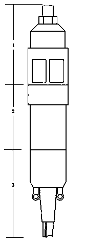
Cross-well sparker source emission probe
A technology of transmitting probe and electric spark, applied in the field of transmitting probe, can solve the problems of short repeated transmitting life of probe, unstable synchronization trigger signal delay, unadjustable transmitting frequency, etc., so as to reduce equipment maintenance and replacement costs, stability and repetition. Increased number of launches and cost savings
- Summary
- Abstract
- Description
- Claims
- Application Information
AI Technical Summary
Problems solved by technology
Method used
Image

Examples
Embodiment Construction
[0017] The present invention will be further described below in conjunction with drawings and embodiments.
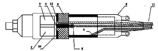
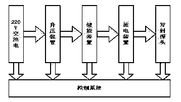
[0018] Such as figure 1 As shown, the electric spark seismic source is mainly boosted by the booster device to boost the 220V AC to several thousand volts of high-voltage DC, charge the energy storage device, and store the energy used for the excitation of the seismic source. After the energy storage of the energy storage device reaches a certain amount of energy, the control system When the launch command is given, the discharge device will close the switch and connect the electrodes after receiving the launch command, and use the energy storage device to store electric energy to the electrodes in the water (that is, figure 1 Composing the transmitting probe in the block diagram) the instantaneous discharge is converted into mechanical energy to generate seismic waves. At the same time, the electrode discharge generates electric sparks, and the optical signal of the s...
PUM
 Abstract
Description
Claims
Application Information
 - R&D
- Intellectual Property
- Life Sciences
- Materials
- Tech Scout
- Unparalleled Data Quality
- Higher Quality Content
- 60% Fewer Hallucinations
Browse by: Latest US Patents, China's latest patents, Technical Efficacy Thesaurus, Application Domain, Technology Topic, Popular Technical Reports.
© 2025 PatSnap. All rights reserved.Legal|Privacy policy|Modern Slavery Act Transparency Statement|Sitemap|About US| Contact US: help@patsnap.com