Single winding hybrid outer rotor magnetic levitation switched reluctance motor for flywheel battery

A technology of switched reluctance motor and flywheel battery, which is applied in the direction of holding devices and electrical components using magnetic attraction or thrust, can solve the problems such as the difficulty in guaranteeing the suspension bearing capacity and stability, the large size of the flywheel battery, and the increase in the volume of the whole machine. , to achieve the effect of improving radial bearing capacity and suspension stability, reducing system volume and high power density

Inactive Publication Date: 2014-03-12
JIANGSU UNIV
View PDF6 Cites 6 Cited by
  • Summary
  • Abstract
  • Description
  • Claims
  • Application Information

AI Technical Summary

Problems solved by technology

[0003] High-speed motors for flywheel batteries usually use traditional motors such as permanent magnet motors, switched reluctance motors, and asynchronous motors. However, since traditional motors can only perform energy conversion, flywheel batteries must be equipped with independent units such as flywheel rotors and magnetic suspension bearings, resulting in the volume of flywheel batteries. Large, high cost, high energy consumption
In order to improve the energy storage density and energy storage efficiency of the flywheel battery, the high-speed motor for the flywheel battery can also adopt a magnetic levitation motor integrating energy conversion and suspension support, such as the magnetic levitation switched reluctance motor with the patent application number CN201210139344.1 and the patent application No. CN201210200147.6 split type magnetic levitation switched reluctance motor, these two kinds of magnetic levitation switched reluctance motors all adopt double-winding inner rotor structure, the defect of these two kinds of magnetic levitation switched reluctance motors is: when the flywheel battery is in standby mode, the main winding and the The suspension winding must work at the same time to generate the required suspension support force, the no-load loss is large, and the insulating material between the main winding and the suspension winding leads to low slot fullness, large magnetic flux leakage of the motor, and low reliability; secondly, because the motor and the flywheel The rotors are placed separately, the axial length of the flywheel rotor increases, and the volume of the whole machine increases; again, the suspension force is greatly affected by the position angle of the rotor, and the suspension bearing capacity and stability are difficult to guarantee

Method used


Image

  • Single winding hybrid outer rotor magnetic levitation switched reluctance motor for flywheel battery
  • Single winding hybrid outer rotor magnetic levitation switched reluctance motor for flywheel battery
  • Single winding hybrid outer rotor magnetic levitation switched reluctance motor for flywheel battery

Examples


Embodiment Construction

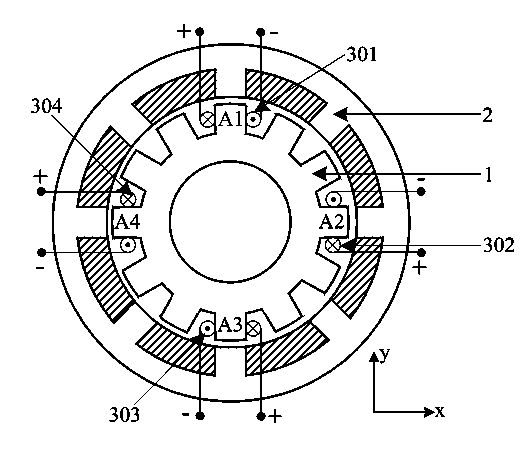
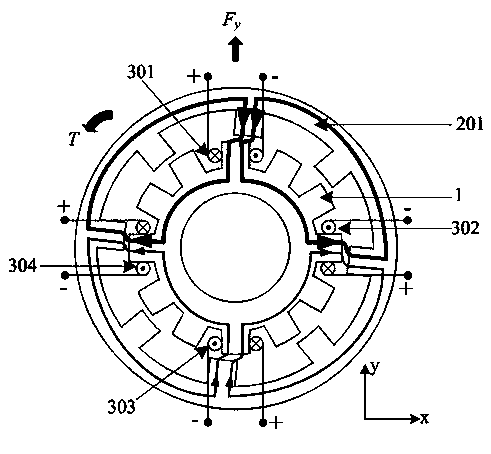
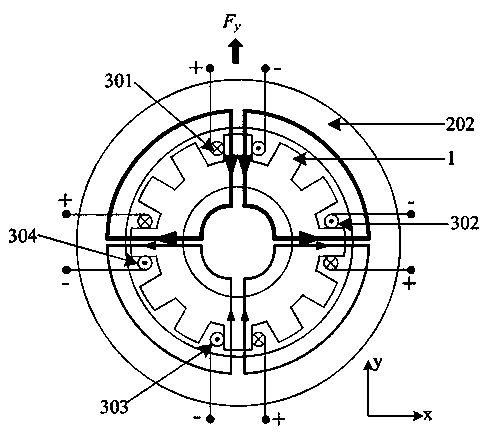
[0020] see figure 1 , the present invention includes: a stator 1, a hybrid outer rotor 2 and concentrated windings. The mixing outer rotor 2 is sleeved outside the stator 1, and both the stator 1 and the mixing outer rotor 2 are coaxial with the rotating shaft. Both the stator 1 and the hybrid outer rotor 2 are made of laminated silicon steel sheets, the tooth poles of the stator 1 are wound with concentrated windings, and the hybrid outer rotor 2 has no windings.

[0021] The present invention only takes a three-phase 8 / 12-pole hybrid outer rotor magnetic levitation switched reluctance motor as an example, and the number of poles of the stator 1 and the hybrid outer rotor 2 can also be 6 / 4, 8 / 6, 12 / 8. The structural diagram of the three-phase 8 / 12-pole hybrid external rotor magnetic levitation switched reluctance motor is as follows: figure 1 shown. There are 12 evenly distributed tooth poles on stator 1, and there is only one winding on each stator tooth pole. The phase A...


PUM


Abstract

The invention discloses a single winding hybrid outer rotor magnetic levitation switched reluctance motor for a flywheel battery. A hybrid outer rotor is disposed outside a stator. The hybrid outer rotor is encapsulated on the inner side of a flywheel in an overlying manner and integrally combined with a flywheel rotor. The hybrid outer rotor is of an integrated structure axially formed by a salient pole rotor and a disc rotor. No windings exist on the hybrid outer rotor. Toothed poles are evenly distributed on the salient pole rotor. No salient poles exist on the disc rotor side. The disc rotor is disposed on the gravity side close to the flywheel rotor. The axial length of the salient pole rotor is 1-4 times of that of the disc rotor. The single winding hybrid outer rotor magnetic levitation switched reluctance motor has the advantages that by the differential excitation of radial anti-pole winding, radial controllable levitation of the flywheel can be achieved, mechanical-electric energy conversion can be achieved, levitation support force, power generating efficiency and motor power density are increased effectively, and the winding and switch inverter circuit structure is simplified.

Description

technical field [0001] The invention relates to a magnetic levitation switched reluctance motor, in particular to a single winding hybrid outer rotor magnetic levitation switched reluctance motor used for a flywheel battery. Background technique [0002] A flywheel battery is an electromechanical energy conversion device. It can convert the electric energy input from the outside into the kinetic energy of the high-speed rotating flywheel through the motor and store it; it can convert the kinetic energy of the high-speed rotating flywheel into electric energy through the generator and transmit it to the external load; it can maintain high-speed rotation in the standby state The kinetic energy of the flywheel without exchanging energy with the outside world. Therefore, high-speed motors for flywheel batteries must not only have the characteristics of electric / power generation integration, but also have the characteristics of high efficiency, high reliability, and low no-load ...

Claims


Application Information

Patent Timeline
Patent Type & Authority Applications(China)
IPC IPC(8): H02N15/00
Inventor 项倩雯孙玉坤嵇小辅吉敬华
Owner JIANGSU UNIV
Why Eureka
Try Eureka