High temperature ejector

An ejector and high-temperature technology, applied in the field of ejector, can solve the problems of calcium carbide furnace gas fluctuation, large fluctuation of furnace gas, long flue of calcium carbide furnace gas, etc., to ensure mechanical performance and stability, eliminate temperature difference stress, The effect of improving the work rate

Active Publication Date: 2015-05-20
CHINA TIANCHEN ENG +1
View PDF6 Cites 1 Cited by
  • Summary
  • Abstract
  • Description
  • Claims
  • Application Information

AI Technical Summary

Problems solved by technology

[0003] Although with the development of my country's economy, the currently used furnace gas purification method is mainly based on the introduction of ELkem technology and has achieved certain success, but there are still the following problems that need to be improved and resolved: (1) due to the The characteristics of long gas flue, large furnace gas fluctuations, and high dust and tar content in the furnace gas lead to frequent changes in the pressure drop of the negative pressure heat exchange system. The furnace pressure is difficult to control only through the flue regulating valve or the frequency conversion of the rough furnace gas fan Realize relative stability of furnace pressure
(2) Traditional furnace gas purification uses negative pressure heat exchange, and the heat exchange uses an air cooler, which leads to extremely high requirements on the material and sealing of the equipment. If the air will be sucked into the heat exchanger due to equipment aging and other reasons, this will It is easy to cause explosion and there is a serious safety hazard
(3) Due to the influence of the operation of the calcium carbide furnace, the gas volume of the calcium carbide furnace fluctuates relatively large and frequently, resulting in extremely unstable operation of the fan and bag filter, making the equipment easily damaged and shortening the service life of the bag filter

Method used


Image

  • High temperature ejector
  • High temperature ejector

Examples


Embodiment Construction

[0011] The present invention will be described in detail below in conjunction with the accompanying drawings and specific embodiments.

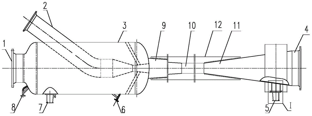
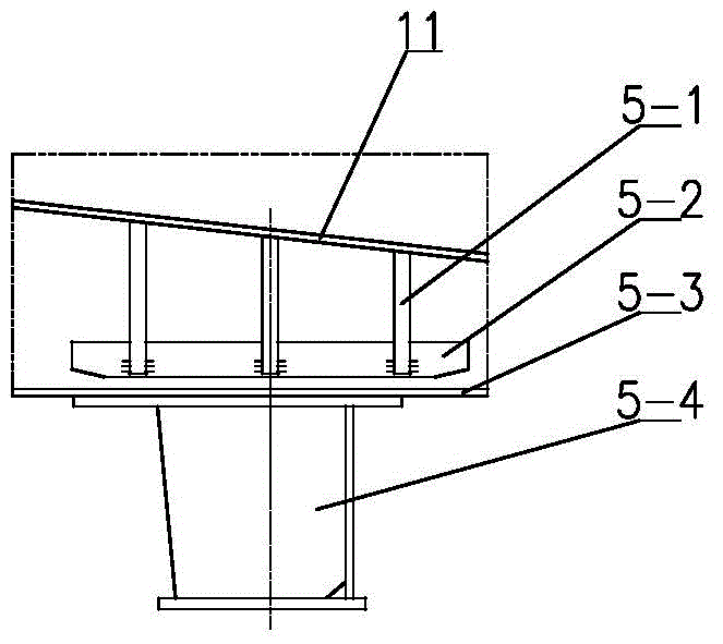
[0012] As shown in the accompanying drawings, a high-temperature ejector of the present invention includes an ejector housing 3 arranged in sequence along the horizontal direction, a first tapered pipe section 9, an equal-diameter pipe section 10, and a second tapered pipe section 11. The diameter of the rear end of the first tapered pipe section is smaller than the diameter of the front end, the diameter of the rear end of the second tapered pipe section is larger than the diameter of the front end, and a furnace gas suction port 1 is installed at the front end of the ejector shell. A furnace gas outlet 4 is installed at the rear end of the conical pipe section, and the power booster pipe 2 is inserted from the ejector housing 3 into the ejector housing 3. The outlet of the power booster pipe 2 is set at the ejector At the communication poin...


PUM


Abstract

The invention discloses a high temperature ejector. The high temperature ejector comprises an ejector shell, a first cone pipe section, an isometric pipe section and a second cone pipe section which are sequentially communicated with one another, wherein the diameter of the rear end of the first cone pipe section is less than that of the front end of the first cone pipe section; the diameter of the rear end of the second cone pipe section is greater than that of the front end of the second cone pipe section; the front end of the ejector shell is provided with a furnace gas suction inlet, and the rear end of the second cone pipe section is provided with a furnace gas exhaust hole; a power pressure inlet is inserted into the ejector shell from the outside of the ejector shell, and the outlet of the power pressure inlet is arranged on a communicating part of the ejector shell and the first cone pipe section; the outlets of first and second protective nitrogen gas input pipes outside the ejector shell are communicated with the ejector shell; the ejector shell is supported and fixed on a first fixed support, and the second cone pipe section is arranged on a sliding support in a supporting manner. The high temperature ejector provided by the invention has the advantages that the negative pressure purification of furnace gas is changed into positive pressure purification, the furnace pressure of a calcium carbide furnace is relatively stable, the operation rate of the calcium carbide furnace is improved, and the yield is increased.

Description

technical field [0001] The invention relates to an ejector in a high-temperature operating environment in a large-scale sealed calcium carbide furnace gas purification process. Background technique [0002] Traditional calcium carbide furnace gas purification generally adopts negative pressure heat exchange, and then sends bag filter for dust removal and purification. 3 , The high-temperature furnace gas with a temperature of 600-800°C (instantaneously 1000°C) is sent to the first-stage empty tower + second-stage cyclone cooling for cooling, and the temperature of the calcium carbide furnace gas is controlled to be ≤250°C. The bag dust collector performs dust removal and purification, and the purified calcium carbide furnace gas is pressurized and sent out to the boundary area of ​​the device. [0003] Although with the development of my country's economy, the currently used furnace gas purification method is mainly based on the introduction of ELkem technology and has achi...

Claims


Application Information

Patent Timeline
Patent Type & Authority Patents(China)
IPC IPC(8): B01D46/42
Inventor 马立全耿玉侠曲建平张梦娣李勇汤明伟孔祥武李洪深
Owner CHINA TIANCHEN ENG
Why Eureka
Try Eureka