
Novel spiral classifier lower supporting device

A spiral classifier and support device technology, applied in the direction of solid separation, wet separation, chemical instruments and methods, etc., can solve the problems of damage to the connecting shaft and support, easy wear of the support and shaft, and high failure rate of the classifier. Achieve convenient maintenance, reduce maintenance costs, and reduce downtime

Inactive Publication Date: 2014-03-19
江西江钨钴业有限公司
View PDF6 Cites 0 Cited by
  • Summary
  • Abstract
  • Description
  • Claims
  • Application Information

AI Technical Summary

Problems solved by technology

Due to the working conditions and structural limitations of the spiral classifier, its lower supporting device has been submerged in the pulp for a long time to work, while the traditional lower supporting device includes a seat body, a circular screw hole is set on the seat body, and there is a bearing in the screw hole, and the bearing is inserted. The connecting shaft at the end of the hollow shaft of the spiral classifier rotates relative to the screw hole, and the rotating surface is in direct contact with the pulp, so the pulp easily seeps into the screw hole from the gap, causing the support and shaft to be easily worn, which affects the design, Inconvenience in use and maintenance, high failure rate, frequent and time-consuming maintenance during the operation of the classifier, which has a great impact on production
In order to reduce wear and tear, the Chinese patent with the publication number CN202733344U discloses a lower support of a spiral classifier. The support has a compression screw hole on the support body, and a screw hole with the end of the hollow shaft of the spiral classifier is fixed in the screw hole. The rubber bushing matching the connecting shaft replaces the bearing mechanism in the compression screw hole through the rubber bushing, which can effectively prevent the slurry from entering the compression screw hole, but the connecting shaft at the end of the hollow shaft rotates for a long time with the rubber There will also be friction between the shaft sleeves, which will also cause damage to the connecting shaft and the support

Method used


Image

  • Novel spiral classifier lower supporting device
  • Novel spiral classifier lower supporting device

Examples


Embodiment approach

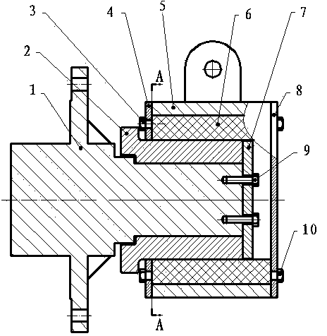
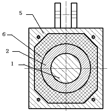
[0013] A new type of lower support device for a spiral classifier, including a shaft head 1 and a lower support body 5, the cavity on the lower support body is square, and a shaft sleeve 2 is installed on the shaft head 1, and a shaft sleeve 2 It is fixed together with the shaft head 1 through the sleeve fixing part 7 and the bolt 9.

[0014] As shown in the figure, the lower shaft head 1 is equipped with a shaft sleeve 2, the shaft head 1 and the shaft sleeve 2 are fixed by the shaft sleeve fixing part 7 and the shaft sleeve 2, and the shaft head 1 and the shaft sleeve 2 are limited. The relative radial and axial movement; the cavity of the lower support base 5 and the shaft head 1 on which the sleeve 2 is installed is filled with wear-resistant packing 6, and the lower shaft head 1 is in the wear-resistant packing 6 relative to the cavity Rotational movement; the packing gland with holes 4 and the packing gland with blind holes 8 are installed and fixed on the lower supporti...


PUM


Abstract

The invention discloses a novel spiral classifier lower supporting device which comprises a shaft head and a lower supporting seat. A square hole cavity is formed in the lower supporting seat, a shaft sleeve is mounted on the shaft head, and the shaft sleeve and the shaft head are fixed together through a fastener and a bolt. Mutual abrasion of the lower shaft head and the lower supporting seat of a classifier can be effectively avoided, failure is greatly decreased, the shaft sleeve and wear-resistant packing are conveniently replaced, downtime of the spiral classifier can be greatly shortened, and maintenance cost is reduced.

Description

technical field [0001] The invention relates to a spiral classifier, in particular to a support structure for the lower part of the spiral classifier. Background technique [0002] Spiral classifier is one of the common equipment in metallurgy, mining and other industries. It is a kind of equipment for mechanical classification based on the principle of different specific gravity of solid particles and different sedimentation speed in liquid. Due to the working conditions and structural limitations of the spiral classifier, its lower supporting device has been submerged in the pulp for a long time to work, while the traditional lower supporting device includes a seat body, a circular screw hole is set on the seat body, and there is a bearing in the screw hole, and the bearing is inserted. The connecting shaft at the end of the hollow shaft of the spiral classifier rotates relative to the screw hole, and the rotating surface is in direct contact with the pulp, so the pulp ea...

Claims


Application Information

Patent Timeline
IPC IPC(8): B03B5/52
Inventor 梁增焕陈志中刘国燕叶志宏
Owner 江西江钨钴业有限公司
Learn More